|
|
Joined: Apr 2004
Posts: 3,555 Likes: 34
1000 Post Club
|
OP

1000 Post Club
Joined: Apr 2004
Posts: 3,555 Likes: 34 |
Putting this where non members can see it.
4th annual open house scheduled for Sat April 7th. If you are interested in going. Email tom@12bolt.com We need a count for tables , chairs, food and drink.
When- April 7st 9AM -whenever
Where-Tom Lowe Shop Dysart , Iowa
What to bring. Yourself and any Inline interested people. And your own BS. Bring any items you want to sell or trade with other Inliners. Bring interesting items to just show and tell.
Contact Tom by email or call. We need to get proper head count for food/ drink/ tables and chairs.
Email tom@12bolt.com
Call 319 476 2172
Last edited by tlowe #1716; 04/05/18 10:40 AM.
Inliner Member 1716 65 Chevelle Wagon and 41 Hudson Pickup Information and parts www.12bolt.com
|
|
|
|
|
Joined: Apr 2004
Posts: 3,555 Likes: 34
1000 Post Club
|
|
OP
1000 Post Club
Joined: Apr 2004
Posts: 3,555 Likes: 34 |
Who took pics? I only got pics from the early morning before people showed up.
Inliner Member 1716 65 Chevelle Wagon and 41 Hudson Pickup Information and parts www.12bolt.com
|
|
|
|
|
Joined: Apr 2004
Posts: 3,555 Likes: 34
1000 Post Club
|
|
OP
1000 Post Club
Joined: Apr 2004
Posts: 3,555 Likes: 34 |
Here are the pics I took. About 7:30 AM before anyone was there. First guy there was from Indiana at 8:30 and he was the last one there too! Had attendance from Iowa, Illinois, Wisconsin, Indiana, Ohio and Manitoba Canada. My Boy had 1 Job, take pictures, here is what he got. 1 picture. He said there was too many guy's to talk to. All in all a good day. Did a demo of boring a 292 block on the CNC. It was fun to see about 25 guy's all try to get a peek into the machine at the same time. 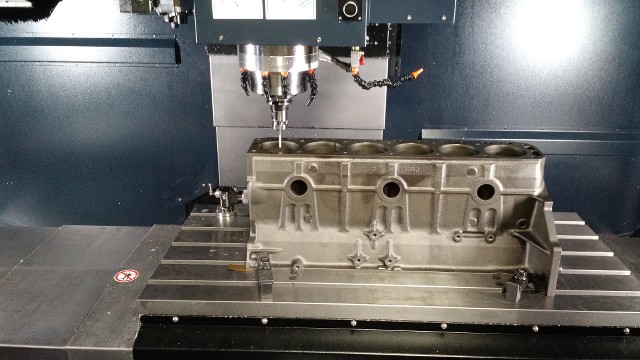 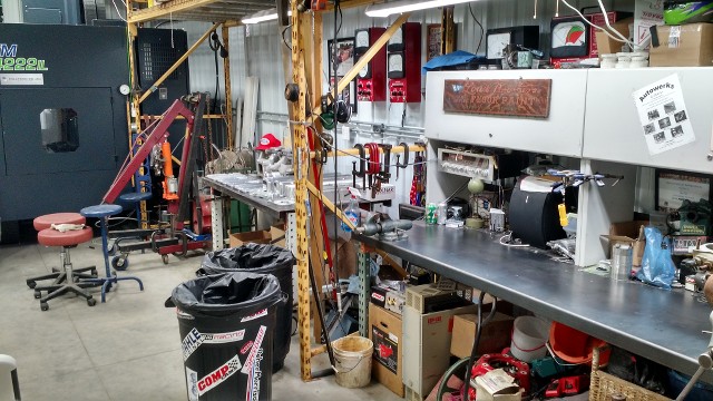 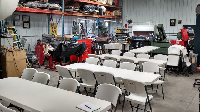  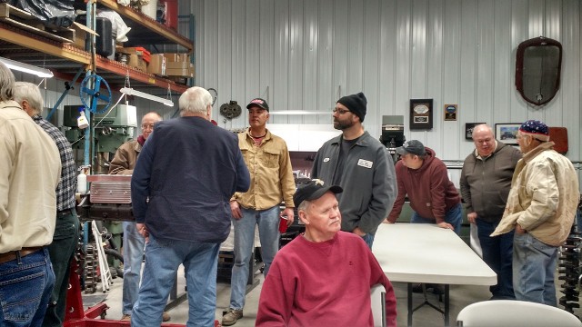 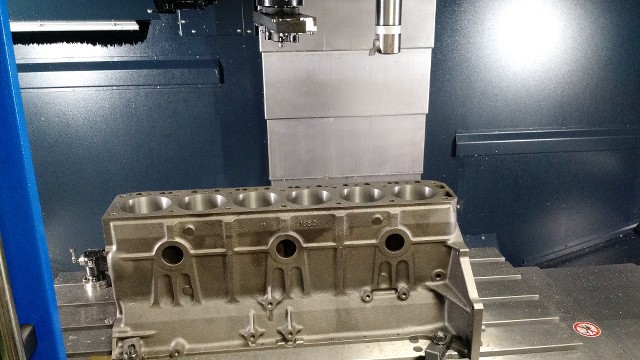 Maybe someone else took some.
Inliner Member 1716 65 Chevelle Wagon and 41 Hudson Pickup Information and parts www.12bolt.com
|
|
|
|
|
Joined: Oct 2007
Posts: 5,015 Likes: 47
1000 Post Club
|
|
1000 Post Club
Joined: Oct 2007
Posts: 5,015 Likes: 47 |
These young people now days, you just can't depend on them.  Nice spread, cool stuff.
Last edited by Beater of the Pack; 04/08/18 12:13 PM.
"I wonder if God created man because he was disappointed in the monkey?" Mark Twain
|
|
|
|
|
Joined: May 2009
Posts: 493
Contributor
|
|
Contributor
Joined: May 2009
Posts: 493 |
Tom, perhaps this is your future plan, if so, apologies. I suggest you use the main bearing bores to mount the block in your milling machine instead of the pan rail. I can send you a pic of the way I did it if you want. This will reduce your setup time considerably. Plus you can't really find the main bearing bores with your current setup and therefore don't know where you are relative to the crankshaft.
|
|
|
|
|
Joined: Apr 2004
Posts: 3,555 Likes: 34
1000 Post Club
|
|
OP
1000 Post Club
Joined: Apr 2004
Posts: 3,555 Likes: 34 |
Good eye, but not quite good enough.
Here is what I do.
The block is measured at front and rear for deck height from the main bearing upper saddles. These are recorded.
The block is then installed in CNC so deck will be flat milled to the deck measurements that were taken. If you could seen good enough, there are shims under the block to do just that.
Inliner Member 1716 65 Chevelle Wagon and 41 Hudson Pickup Information and parts www.12bolt.com
|
|
|
|
|
Joined: Apr 2003
Posts: 1,537 Likes: 15
1000 Post Club
|
|
1000 Post Club
Joined: Apr 2003
Posts: 1,537 Likes: 15 |
But what establishes the center of each bore?
|
|
|
|
|
Joined: Jan 2005
Posts: 2,123 Likes: 3
1000 Post Club
|
|
1000 Post Club
Joined: Jan 2005
Posts: 2,123 Likes: 3 |
|
|
|
|
|
Joined: Sep 2008
Posts: 3,669 Likes: 42
1000 Post Club
|
|
1000 Post Club
Joined: Sep 2008
Posts: 3,669 Likes: 42 |
But what establishes the center of each bore? You as the operator have to indicate each cylinders centerline yourself and also touch the tool off at some designated height you determine and then designate a work offset in the CNC control panel to represent each cylinder and also the tool height, so when you create the program the tool knows where to go and how far to travel up or down so it won't crash into the block. Its all part of the setup process you have to do each time you start a new part.
Class III CNC Machinist/Programmer
|
|
|
|
|
Joined: Apr 2004
Posts: 3,555 Likes: 34
1000 Post Club
|
|
OP
1000 Post Club
Joined: Apr 2004
Posts: 3,555 Likes: 34 |
Stock 49,
I have a probe that checks each bore at a depth that I have programmed. It finds the center of each individual bore and saves it. Then go back and bore the locations to the depth I tell it in setup. 12 minute program and not even trying to rush it.
There are about 10 different ways it could be done, this is just one of them. Another is to bore it to blue print specs.
Last edited by tlowe #1716; 04/11/18 12:16 AM.
Inliner Member 1716 65 Chevelle Wagon and 41 Hudson Pickup Information and parts www.12bolt.com
|
|
|
|
|
Joined: Apr 2003
Posts: 1,537 Likes: 15
1000 Post Club
|
|
1000 Post Club
Joined: Apr 2003
Posts: 1,537 Likes: 15 |
Thanks for taking time to explain. I follow you in how the probe can orient the machine to the work piece. But to strokersix's question - what orients the boring center-lines with the crank throw's when attaching the block to the fixture?
|
|
|
|
|
Joined: Sep 2008
Posts: 3,669 Likes: 42
1000 Post Club
|
|
1000 Post Club
Joined: Sep 2008
Posts: 3,669 Likes: 42 |
It doesn't have to be, the cylinders are bored relative to themselves. Companies like BHJ make Block truing plates that you bolt to the deck like a torque plate that you indicate to replicate a more precision placement of the bores like the factory blueprint bore positioning and bore centerlines. But you run the risk of offsetting the bore enough that it won't clean up at a .030" bore size if there is a lot of ring wear at the top of the cylinder.
Since the cylinders are bored originally and correctly from GM, centering up on them will get you as close as you'll ever need to be. They used NC machining procedures when they made them also.
Class III CNC Machinist/Programmer
|
|
|
|
|
Joined: May 2009
Posts: 493
Contributor
|
|
Contributor
Joined: May 2009
Posts: 493 |
My comments below are not meant for Tom. Rather responding to other comments.
Picking up deck features and existing bores is good enough for most. But are you sure? What if your block is already at .030 and been decked. Do you trust the previous work?
You should start with the fundamental geometry which is the crankshaft main bores. Then if you need to make adjustment for casting shift, bore wear, angle decking, or whatever other reason you can do so with understanding of where you are from the crank.
|
|
|
|
|
Joined: Jan 2005
Posts: 2,123 Likes: 3
1000 Post Club
|
|
1000 Post Club
Joined: Jan 2005
Posts: 2,123 Likes: 3 |
Do you trust the previous work?
I agree
|
|
|
|
|
Joined: Sep 2008
Posts: 3,669 Likes: 42
1000 Post Club
|
|
1000 Post Club
Joined: Sep 2008
Posts: 3,669 Likes: 42 |
True...true! Knowing where you are based on a baseline reference is beneficial.
Class III CNC Machinist/Programmer
|
|
|
|
|
Joined: Sep 2008
Posts: 3,669 Likes: 42
1000 Post Club
|
|
1000 Post Club
Joined: Sep 2008
Posts: 3,669 Likes: 42 |
Looks like you got a new Milltronics mill. Looks good!
Class III CNC Machinist/Programmer
|
|
|
|
0 members (),
268
guests, and
45
robots. |
|
Key:
Admin,
Global Mod,
Mod
|
|
|
|