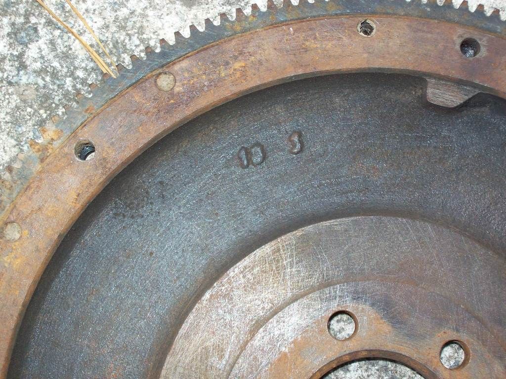
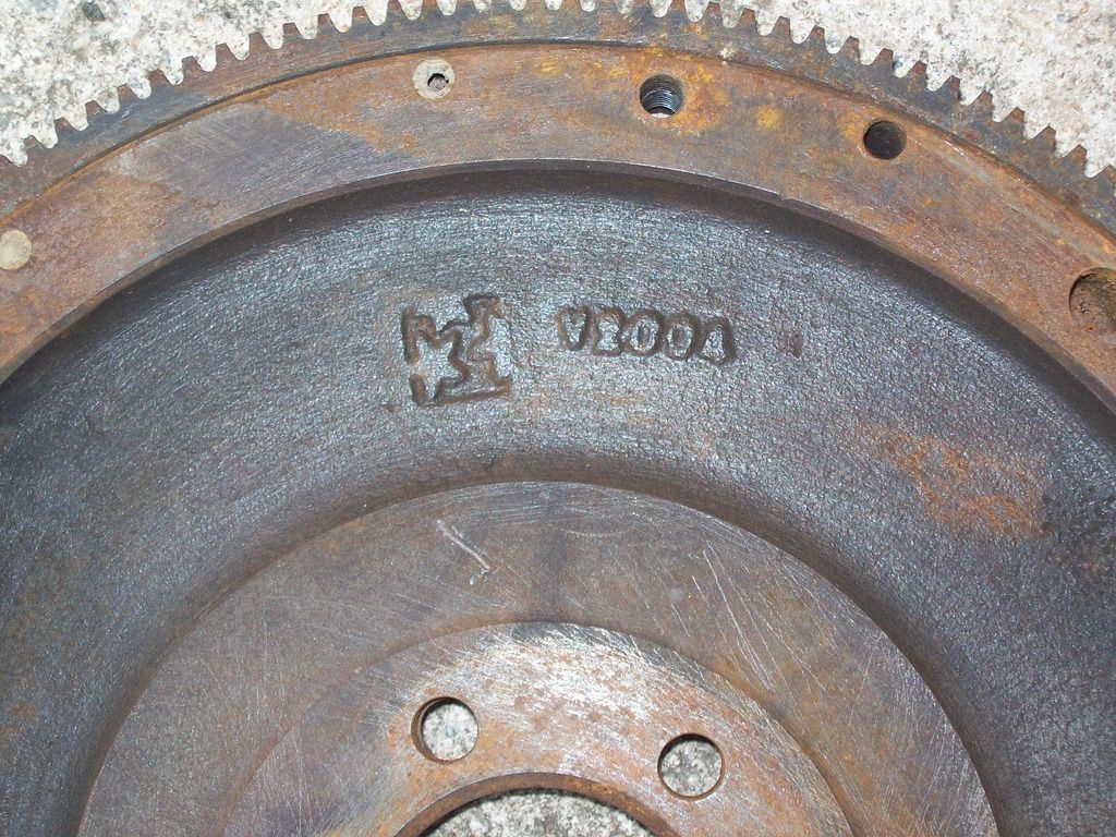
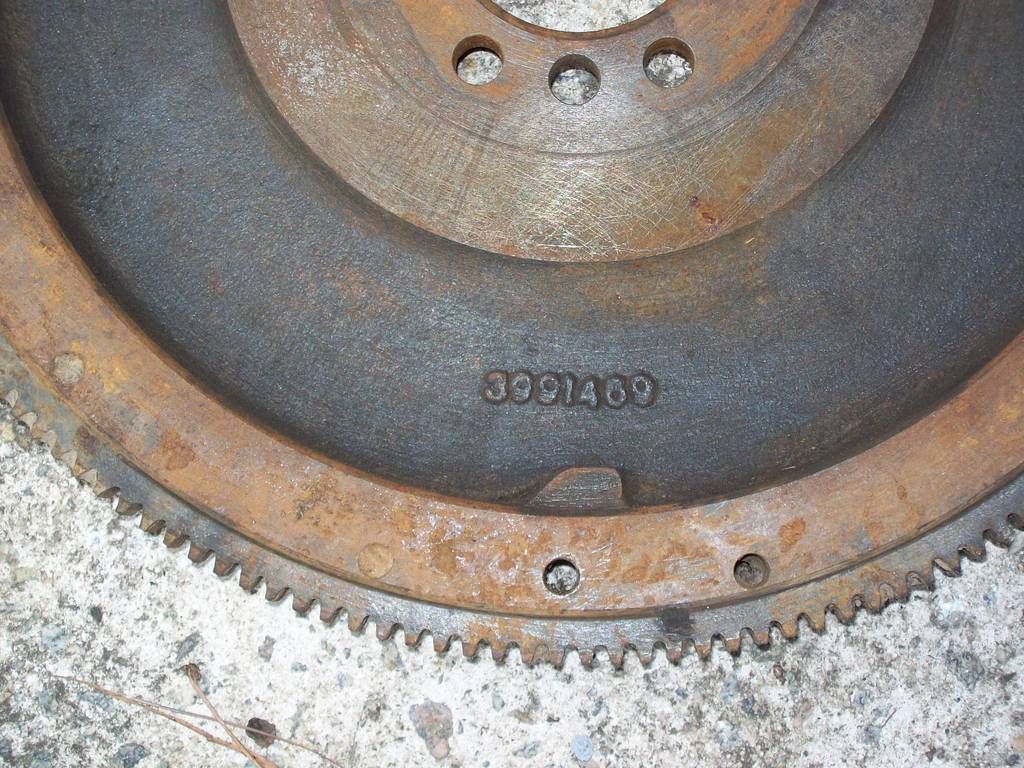
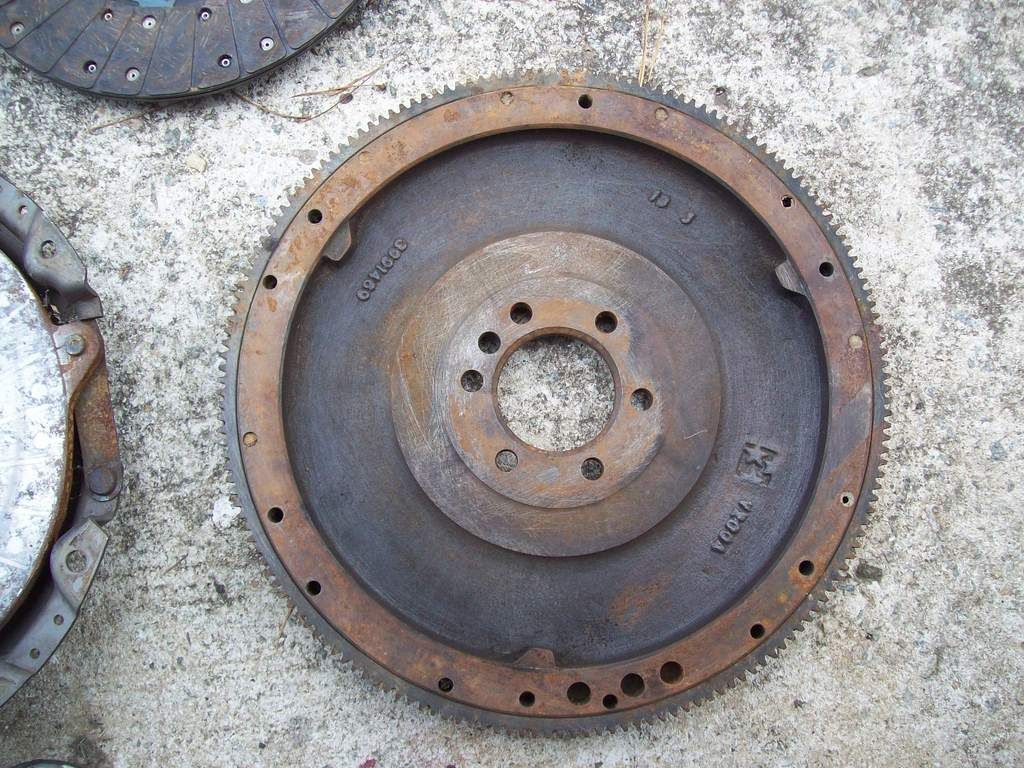
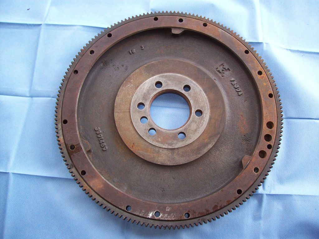
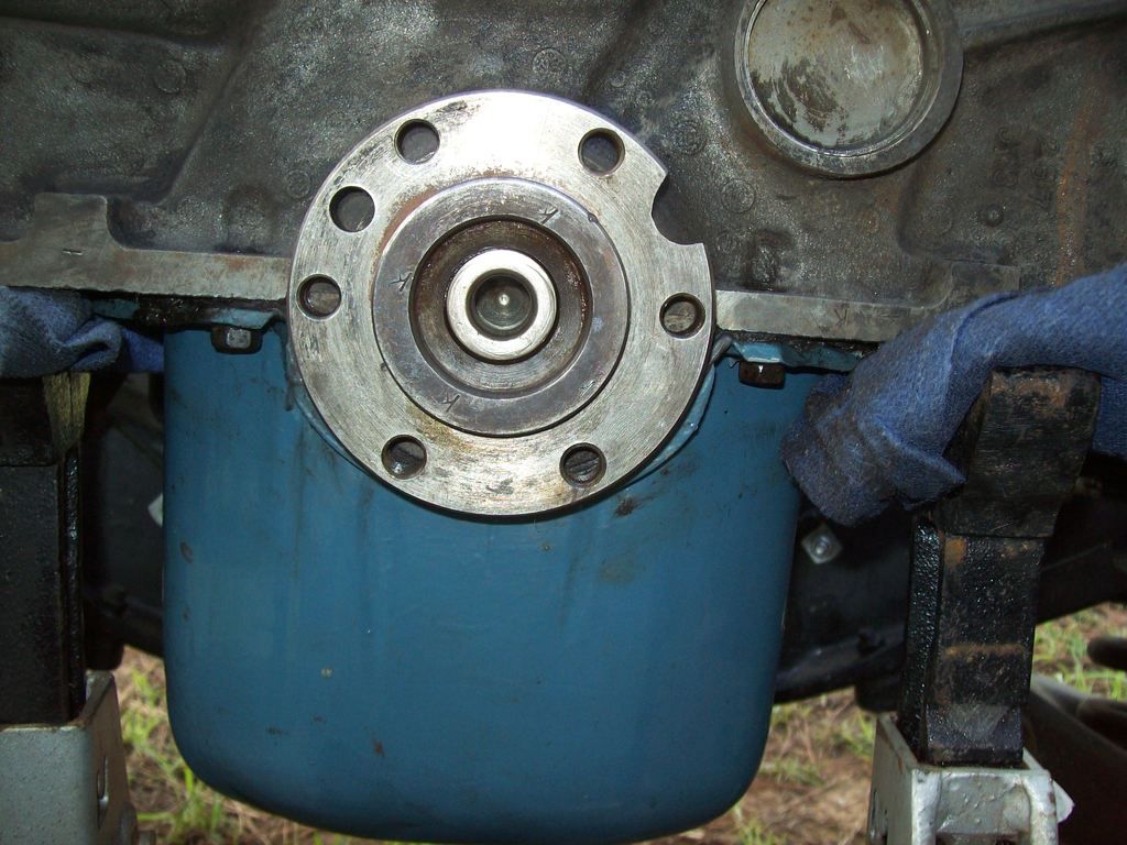
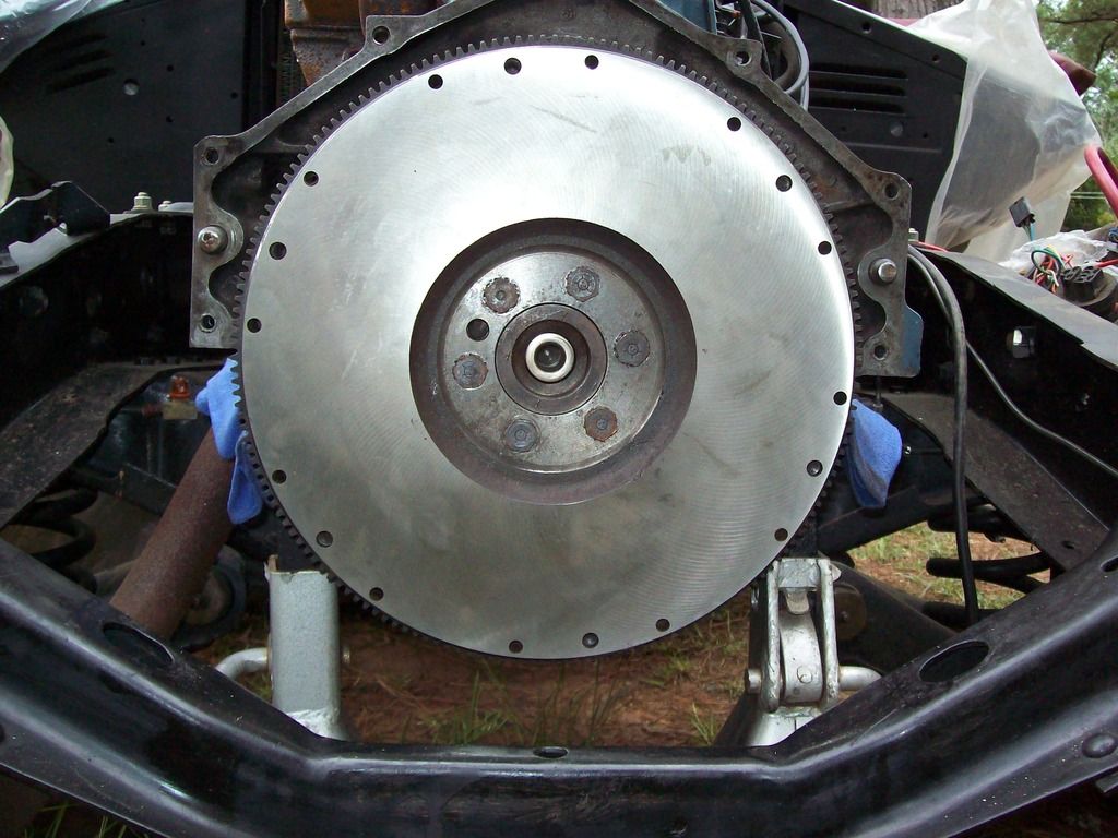
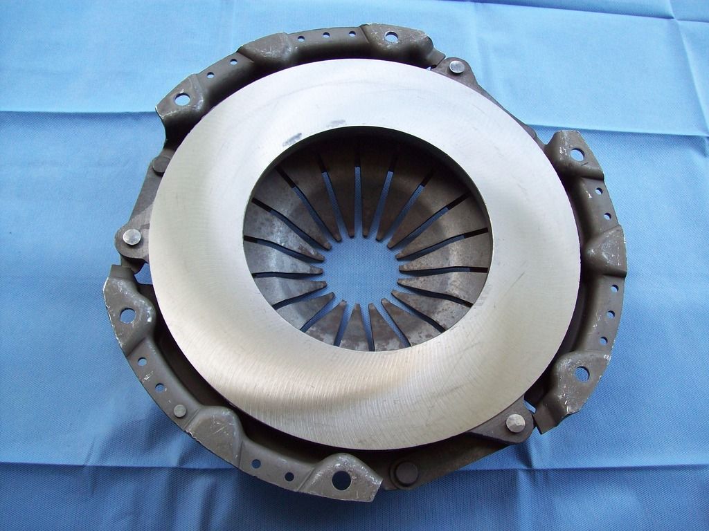
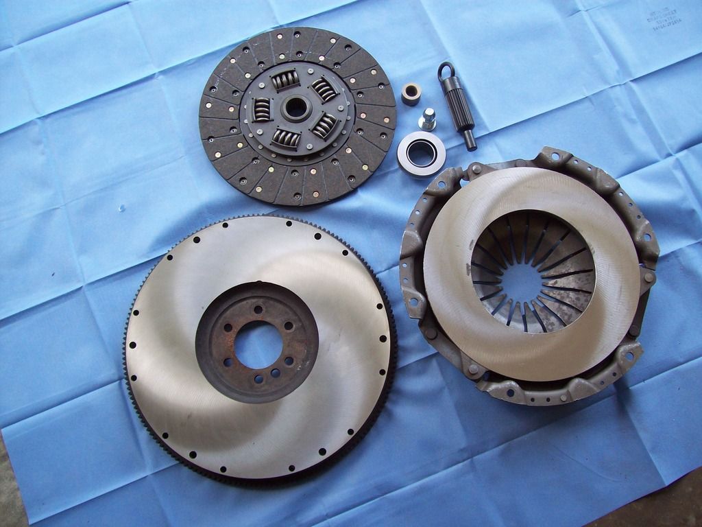
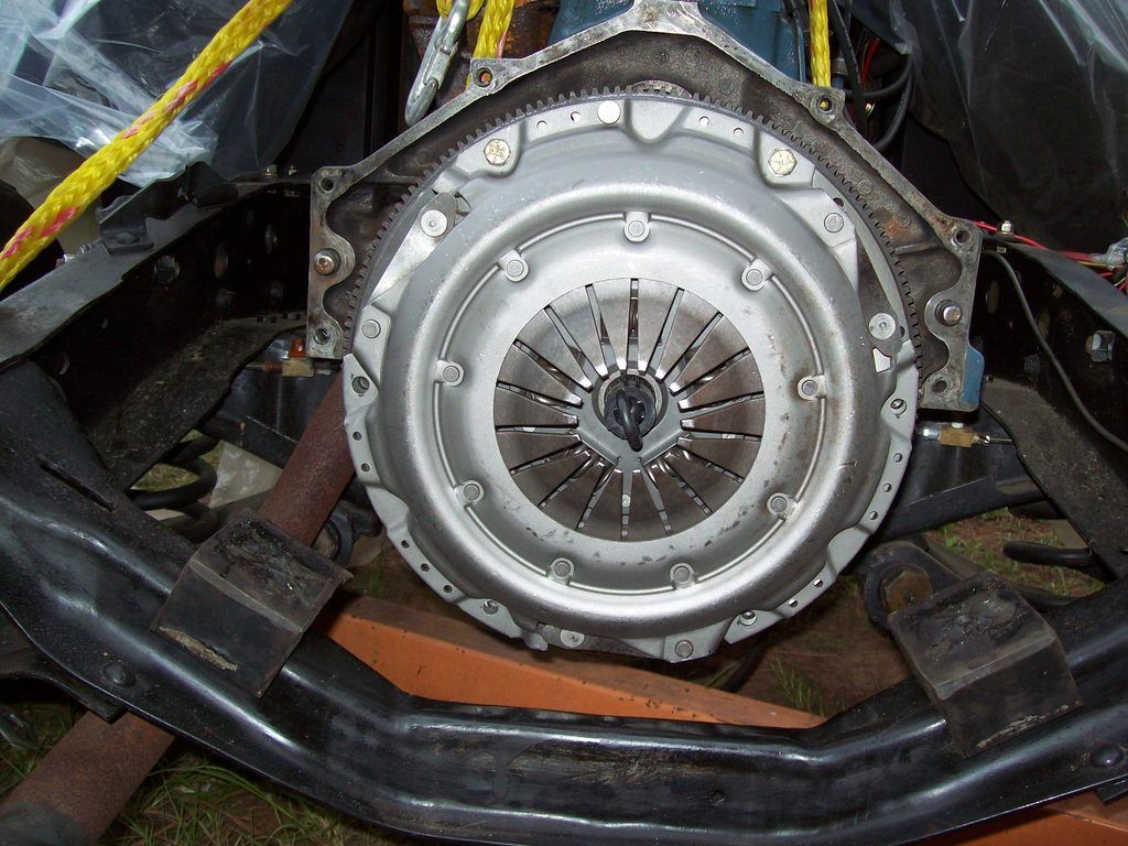
I will soon be putting the flywheel back on my 261. Somewhere there was a how-to that showed how and where to mark a 235/261 flywheel with extra marks showing where to adjust the valves. Can someone tell me where to find it again? thanks
I have always done the valve adjustments at the TDC mark only to do the first half of the valves, then a 360 rotation back to the mark again to do the other valves. TDC is the line between the UIC marking.
Adjusting the valves on a six is EASY. For beginners I recommend writing down the firing order, 153624, thusly:
1 5 3
6 2 4
With a breaker bar or long handled ratchet and a crank socket rotate the engine damper until the timing mark comes up to top dead center. Watch #6 cyls and #1 cyls rocker arms as you do this. On one of these two cylinders the exhaust will just be closing and the intake will start to open as you approach top dead center. If that happens on #6 then adjust #1. If it happens on #1 then adjust #6, because these two pairs are matched, as in the diagram above (5 & 2 and 3 & 4 are the other two matched pairs). So lets say you just adjusted #6. The next cylinder to adjust in the firing order is #2. Rotate the crank about a third of a rev, watching #2's buddy, #5. The exhaust rocker for #5 will be closing and the intake starting to open as you get to TDC. Adjust #2 when the two #5 rockers are in alignment, one closing and one opening.
Continue this process until you go through all six, then go through it again, to double check. With this method you can adjust all six cylinders with only two revolutions of the crank.
To speed things up you could mark your damper or flywheel in three places spaced 120 deg apart. But any more I dont even look at the damper.
With practice you can run through your valves in five minutes. It will take you longer to remove the valve cover than to run the valves. Whats more you wont even have to look at the damper, just find the cylinder in the overlap cycle and start from there, adjusting the buddy cyl. Good luck. THE FRENCHTOWN FLYER
That's actually what I had in mind. The post, wherever it was, showed counting the flywheel teeth and finding, and marking the places to adjust #s 5 & 2, and 3 & 4.
Adjust the valves as above. Much more accurate way of adjusting. btw, you should probably confirm tdc on the flywheel, especially if its not original to the crank/motor. Should be determined with a degree wheel but if not, the old fashioned way will get you pretty close. Line up the timing dots on the crank and cam gear, that is tdc for no. 6. Rotate exactly 180 degrees. The timing dot for the cam gear should be at about 11 o'clock. That is tdc for No. 1. Use a punch or chisel on the crank flange in the back of the motor for future reference. Install flywheel and mark flywheel.
I have always removed the distributor cap, turn the engine and watch for the rotor to point to the cylinder to be adjusted. Is this not a good way of doing it. Dave
No, that method is not accurate at all. The best and most accurate method is to make sure the lifter for the valve you are adjusting is fully on the heel of the cam lobe.
I like to go a little crazy when marking my flywheels and use a sharpie to mark TDC for each of the cylinder pairs. Here is the writeup:
http://devestechnet.com/Home/FlywheelIt will depend on the number of teeth on your flywheel. I have a 261 in an AD with the 6 volt flywheel, so I have to count differently. Hope it helps!
