guys ,
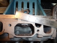
here is something i am going to try on my motor. everyone knows the siamesed ports hurt performance and tuneabilty on our engines. i have built some prototype dividers and installed them in my motor.
some particulars of my motor. it is turbo charged, and injected, i also have bolt in lumps. i have noticed with the injection @ idle the mixture is not equal on cyl's 1,2 and 5,6, it is because of a timing thing. one of the cyl will get more mixture of fuel than the other. it works out better at 1500 rpm or higher.
so i have made these.


give me your thoughts, remember these are prototypes and will be reworks to a higher quality if the idea works. tom
Tom,
It may work.. maybe it'll help if your getting reversion at low rpm.
Have you got your fuel delivery issue worked out?
Just wondering how you are attaching the dividers?
Also,just to let you know,it may help your fuel delivery problem,but it also kill the flow of your intake port.
It makes the intake port window too small.
You would have to widen the ports just to make up some of your lost intake flow,even then it will not flow anywhere near it does with the one big port.
Hate to sound negative,but dividing the ports did not work for me & it did not work for Mike Kirby.
It should help your low-mid range,but it will kill your top end.
Two cents thrown. :-)
MBHD
I agree with MBHD. I also tried dividing the port and the flow fell off drastically on the top end. I took a fly cutter to the face and built my dividers to the flange and bolted the flange to the face.
efi, the only fuel delivery problem is this one. i am trying to direct the fuel from each injector to the correct cylinder.
hank, they are held in by the 1 bolt going from top to bottom in the port. you can see it in the pics. the other bolt is to keep it lined up with the port.
i hope the turbo will help with the loss of flow.
$um fun, when you tried it was your engine N/A or boosted?
i would have tried running it last night , but for some reason the starter refused to work, go figure. maybe that is a sign. tom
The bolt to keep it lined up in the port, that goes into your intake manifold?
My upper lump ports I made attached to the top w/a bolt also,but the back of it goes to each side of the back wall,,,(like a "V" shape) no need for a bolt blocking airflow.
Let us know how it turns out.
MBHD
Tom, I am now using a stock head with welded in dividers before and after the stock head bolt, also in the intake. but I needed over 30 psi to make the same HP. I felt I had to seal mine since I use carbs, you may not need to since yours is injected. Hope I yours works, as good as mine did all the plugs look the same.
Still fighting an issue with mine hope to have it at the covention.
Harry
Tom, My head was NA and when I put it on the flow bench it looked like the flow was almost cut in in half. I took the dividers out and moved more CFM by raising the port and reshaping the combustion chamber, and straighting the runners on the side. This was on a GMC head and when you open the intake ports you run into the head bolts and even with the tubes installed their is some port choke. I think in all we added almost 75-90 pounds of steel with the welder.
had to charge the battery, imagine that, after a whole 8 months of sitting the battery goes dead. better it than me!
went out and it turned no more than 3 times and starts perfect and idles much better than it had in the past. i will get to drive it tomorrow. i bet it will need to be retuned also. better charge up the laptop tonight. tom
Tom, but I needed over 30 psi to make the same HP. I felt I had to seal mine since I use carbs, you may not need to since yours is injected.
Harry
Harry,
how much boost were you using before the dividers? Now 30 psi to make the same power.
Also,how much HP & torque are you making now?
Thanks
MBHD
Hank, was 25# now 34#, 650 to 680 HP close to max of the T70 turbo, in flow and pressure ratio.
Hank, was 25# now 34#, 650 to 680 HP close to max of the T70 turbo, in flow and pressure ratio.
Was that flywheel HP, or rear wheel HP?
Did you get a torque reading?
Thanks.
MBHD
guy's, took the mino out after my boys, coach pitch ball game. my other 2 are also in sports stuff, that can sure kill a evening.
anyway, the engine runs smoother, seems to start better, takes less fuel(good now adays)and will still boil the hides off the tires. it took awhile to get it tuned in (10 minutes). it is weird how the plates changed the tune. the fuel from each injector is directed at the corresponding cylinder and not robbed by it's siamesed twin.
i have a privately made program that patch's in with the holley software. simply turn it on and drive the car around for 10-20 minutes. it reprograms all the fuel points on the go! it dialed in too easy. i then ran it thru the rpm range under full throttle and datalogged it all. the Air Fuel Ratio (AFR) was much more stable. so far for a boosted/port injected inline the dividers seem to be the ticket.
my next question is: do i pull the bolt in lumps to gain back some of the lost port volume?
my next question is: do i pull the bolt in lumps to gain back some of the lost port volume?
The lumps are not hurting anything with your airflow,,,,,Hum,,
But on the other hand it is making your window port small.
Since you are not normally aspirated,intake port design is not as critical since you are forceing air into your intake port.
If it is not that much of a hassle,,,,,,try taking out the lumps & get back to us.
Best thing to do is widen & raise the roof of the intake ports.
The bolt to keeps your dividers lined up in the port, that goes into your intake manifold?
MBHD
Hi Hank.
Do you have pictures of the upper lumps? I didn't understand how they work, can you help me?
Thank you very much!!!
You can take at the very least .050 out of the top of the ports.Same holds true to the sides. Pull .025 from each side to start with. And see what happens then. The lumps still help the
short turn radiuse even under pressure. My personal thought would widen the Ports first. To make you what you may? have lost with the divider.
Larry, thanks!
But I didn't understand. I installed your bolt-in lumps in the bottom of the head ports (they look perfect and it was really bolt-in)

.
So I am asking about the top of the head port lumps. The top of the ports were milled a bit making it flatter. So I install a lump there? It would decrease the intake port volume. I believe this is good if it also has a shape as well as the lumps installed in the bottom. Or not good?
Anyway... Do you have this upper lumps so I can buy again from you? Or they are simple and I can make it?
I am thinking that if I make lumps straight it will reach the valve guide area. Sorry, I am a lot confused.

Also I am not using port dividers and won't use it.
My engine is going good and hope to finish it this year. It is a Chevy 250 normally aspirated for street/strip use.
Thanks a lot!!!
Alex
No not at this time do i make a upper lump. The port if it has not been divided, i do not feel that you need to do anything else
at this time.
The upper lump Hank is talking about that he made went in the
center of the port between the valve guides.
Chevy 250 Opala,
I will take some pics & send to you on the upper lumps.
MBHD
here is my upate on the intake port dividers that i made.
ran thru the summer with them in. many hundreds of miles and lots of full throttle hits. even about 20 runs @ the strip.
engine starts better
idles better
takes less fuel at all speeds
gets off the line better
no more part throttle backfires/ hickups
improved at the strip from a 14.2 to a 13.8 in the 1/4
next i will open up the top of the port and the sides to gain back some port volume or runner size. maybe try to do it yet this year to try it. 2nd , i will pull out the bolt in lumps and keep the dividers to make the runners even larger.
keep in mind, this works well with port fuel injection and a turbo. it probably would not work the same with a carb N/A. tom
tlowe/Tom
The main problem like you are thinking is that the port window are too small w/your dividers.
I think it should run best w/your lower lumps installed & you open up the sides & top of your intake ports,w/your dividers installed.
Now being it's turbocharged (forcing the air into your cylinder head) ,it is not as critical for needed a really nice port design.
It will be interesting to see what works better,my bet is using the lower lumps & opening up your ports over taking out the lower lumps & making the ports bigger..
When you take out your lower lumps & open up the intake ports,you are going to loose a lot of velosity & I would think there goes your lower RPM street drivability.
Having a good short turn radius really helps out w/the airflow & taking out the lower lumps will really hurt it if it was N/A, just not as bad w/your turbo.
The lower lumps also decrease the volume of the intake ports causing the velosity to increase, which in turn gives you better streetability & overall performance,torque.
I keep telling Douglas to install some lower lumps,no luck so far. :-) His car is normally aspirated & I think the lower lumps will help his cause.
MBH
here are some more vids for you all.
http://www.youtube.com/user/telowe2000pic whichever you like. while watching the vids you can pic the high res version and see everything in good detail.
who knows of a freeware video editor? i have more but want to edit. tom
What's that on the hood?
Pretty quick.
i have added 67 chevelle ss style hood bulges added and you may see my temporary fuel guage taped to the wiper. tom
Probably the tape fluttering then (don't feel bad, I've got the boost gauge for our current hauler duct taped to the box, beind the cab

). Gotta love a temorary install.

Hey Tom:
Nice videos!
Hope you don't mind me jumping in on this thread with a question of my own, but maybe it will help others ,too.
In your walkaround, i think i heard you say you were running .030 plug gap to keep the turbo from blowing them out.
I know you have already said it elsewhere, but how much boost you running? I knew you were supposed to run reduced gap for boosted applications, but i didn't realize you needed to go that far. My 250 is running Splitfire coppers (heat range = AC R44XLS) at .046" off a GM HEI, 7PSI boost, and it just seems to smother out at WOT above 4000rpm. I'm running a stock mechanical fuel pump, so I just figured I was running out of gas. Plus, it's a street driver, RARELY revved like that anyhow, so i just haven't been concerned about it. Think plug gap is the culprit??
Thanks for your thoughts.
Generally, you should not need to reduce your spark plug gap to .030 w/only running 12 lbs of boost w/an HEI.
The only times guys reduce there gap down to say about .026 -.028 on there Syclones & Typhoons is when they are dumping in a lot of methanol.
I run a .040 gap on my Syclone w/an HEI ,I also run a MSD 6A box & normally run 17-22 psi range, I have not snuffed out my spark.
Max RPM on stock Syclones is about 4800.
Stock boost pressure on the Syclones & Typhoons is 14 psi,no reason to run a small gap from the factory.
pappy, i am running upto 12 psi boost. it sounds like you are having the same problem i had. close your gaps to .035 and give it a try. if you have a weaker coil and non performance wires then 7 lbs may be enough to blow it out. mine started blowing out the most in 3rd gear at the 4000 and higher rpms. that is where the longest highest load takes place on the engine.
i have more vid's i can put up but my pc software will not see the file type. want to put out another longer walk around vid.
you could still have a fuel problem, you really should boost reference the pump or atleast the fuel pressure.
hank, i put the gaps there because it cured the problem i was plagued with for so long. i could try bumping it back up in gap. but i know .045 caused the problem. .030 cured it. tom
Tom,
if that fixed your problem, no reason to open the gap back up.
I had .045 gap when running my Paxton supercharger & 8-10 PSI turning 7000 RPM, never blew out spark.
HEI's usually are good even when turbo or supercharging, but blowing out the spark @ only up to 12 psi, seems like something is amiss.
Never has anyone w/there stock Sy's/Ty's has had to close up there spark plug gap & like I stated,stock boost is 14 psi.
MBHD
thanks for the ideas, guys.
one of my winter projects was going to be an electric fuel pump, and i'll shorten the gap, too.
pappy,
i want to see some video's of your ride, i know you are needing to get a camera/recorder.
now , back out to the shop! tom
ok
don't give up, it'll probably be after Christmas.
if Santa is good to me.
Hey Tom:
Nice videos!
Hope you don't mind me jumping in on this thread with a question of my own, but maybe it will help others ,too.
In your walkaround, i think i heard you say you were running .030 plug gap to keep the turbo from blowing them out.
I know you have already said it elsewhere, but how much boost you running? I knew you were supposed to run reduced gap for boosted applications, but i didn't realize you needed to go that far. My 250 is running Splitfire coppers (heat range = AC R44XLS) at .046" off a GM HEI, 7PSI boost, and it just seems to smother out at WOT above 4000rpm. I'm running a stock mechanical fuel pump, so I just figured I was running out of gas. Plus, it's a street driver, RARELY revved like that anyhow, so i just haven't been concerned about it. Think plug gap is the culprit??
Thanks for your thoughts.
Well, it's almost a year later, and I finally got around to figuring out my "smotherin" problem: exhaust backpressure!
Uncapped the headers and ran it thru the gears a coupla times and the little 6 screamed!(new videos attached) First time it has ever wanted to wind 5G's!
I had a feeling that was the problem from the way it sounded, but just couldn't believe dual 1 3/4" exaust thru 2" turbo mufflers would be that restrictive for 250ci.
Anyhow, food for thought if you're planning on building a forced induction system.
http://www.youtube.com/watch?v=6mD6nt3SFoUhttp://www.youtube.com/watch?v=Gq8F_cia0ishttp://www.youtube.com/watch?v=JcSBNdM7-Xs
Here's some additional thoughts along the lines of dividing the intake ports. About 10 years ago, most of the top Comp 6 cylinder guys began to abandoned the age old practice of "lump" porting altogether. One close friend of mine from the west coast that moved from Comp Eliminator up to Pro Stock truck at about that time told me recently that he always wanted to try dividing the port, but Headrick and Self and the other "lump" guys said there was no way it would work and not to try it. He told me that I knew he has always had the best "lump" heads money could buy and had used everybodies in the industry. He always ran a 250 inch engine in several of the Econo Altered classes for at least 15 years and set many records and won his share of national events, and he said he wanted to think outside the box one last time before he left the 6 cylinders behind. He took an old brazed "lump" head he had laying around, and ground the lumps completely out of the head, and just ported and shaped the head like you would a conventional V8 head. He then welded some sheetmetal dividers to the end of the intake flanges, after he contoured them to fit the port shape. He freshened the valve job and took the existing "lump" port head off his engine and put on the divided port head, and then dynoed the engine. He again re-emphasized the fact that he had used the very best "lump" heads that were out there....and this divided port head made over 50 more HP than the best "lump" head he ever had, and he set a new record with the car as he wound down his time in Comp with the 6 cylinders. Now more recently, my good friend Sherman Sligh, who is still actively racing and winning with his 250's in Comp Eliminator, also runs a divided port head, and he says the intake ports flow 400 CFM @ .900 lift. This is about 50 CFM better than our best "lump" head that we used on Cotton's engine. I think that it is neat that Sissell created such a niche and legacy with the "lumps" that has lasted so long, but its also ironic, that he could have simply stuck a .10 cent piece of sheetmetal into the port and created an even greater legacy and far superior port....
Any photos? I can imagine but I'd love to see.
Sherman wouldn't give me any pics of his head. But he did describe in great detail all the things he did,even saying it looked like an SB2 port turned on its side. He even reshaped the combustion chamber into the more modern heart-shaped style, and ended up with it at 21cc's. Now he can attain the same compression with a flat top that we were getting with a big dome. His divided port is welded in and blended with generous radius' front to back on both sides of the divider. What Darren told me he did 10 years ago was much cruder, but still had impressive results for no more time and effort than it took him to do it. From his description, after he ground the brazed "lumps" down, it appeared much like a head that is ready to install the bolt-in lumps with just a flat floor with the head bolt boss removed. These heads for the Comp motors have a much wider port than the street bolt-in "lump" heads have, but look very similar when they are at this stage of construction. Darren said he just rolled the short side radius with what material was left after removing the "lumps", and fitted the dividers to fit the shape of the profile vertically(floor to roof) as best he could, still having to make a notch to clear the short bolt in the port floor,and welded it as an extension on the end of the intake port flange. Not being an experienced head porter, Darren is however a very excellent fabricator,his dad has the best aftermarket race header company there is, and Darren at 13 or 14 years of age was building headers, and at 16, was competing in NHRA Super Stock and doing good. Again, Darren's approach seemed a little cruder but the results were enough to get your attention. I think for so long, it was just accepted that the "lumps" were the only way to make these heads flow and perform, and no one was looking to find a "next" level to climb to. I know that was our thinking on it. I am currently doing (2) brazed "lump" heads for a guy in South America that are very similar to Cotton's heads, and I am thinking of experimenting with the divider idea. I'll post some pics and data when I get to that point....
CNC-DUDE,
I remember Darren Davis's altered It was a good running car, but didn't know he had a divided head. I also remember reading about Sherman Sligh but didn't know him. Did he weld up the water jacket side of the port to get more width from the port?
Great info. can you get more?
Harry
Harry, when Darren did this, it was the last few races of the season that he stopped competing in Comp and moved up to Pro Stock Truck. Pro Stock Truck didn't last but just a short season itself, so that can kinda' give you a window as to the time this occured. Prior to that, he had also taken (2) of the aluminum Iron Duke race heads he got from Doc Dixson at the Rod Shop and cut them apart and welded them together to fit his 250. He said that was the most awesome head he had ever had on his engine, but of course it was not legal for Comp(and he knew that),the first time out he blistered the index, and got into tech inspection and NHRA tossed the head out. Thats when he decided to try the divided port idea. He already made up his mind to leave Comp and move up, so he was going to just satisfy his curiousity before he did. As for Sherman, he was an old veteran of the "lump" heads, and it was common to grind into the water jacket to widen and reshape the ports anyway, and they are much wider than the ports you will find on the typical bolt-in "lump" street head. Of course, everything in those heads are much bigger, the valves, bowl area and port height and width. But these are all out race heads, and that is just part of the procedures to get them there. Even with Sherman's and Darren's 250 engines, they still used a 2.150" intake valve like we did with Cotton's 292's. I am curious myself now about the divided port, and will thoroughly test one of the heads I am prepping for the guys in S/A, before I fill the ports with brass, and see what hapens. One head will have only the smaller 2.02" intake valves in it, but the other will have 2.150", so I will be able to flow each valve size from stock all the way up. Im sure with time, Sherman will become more relaxed, and possibly take some photos that I can get from him. The aluminum Iron Duke heads is any easy transplant for the 6's, because they have the same bolt pattern and bore spacing, and will give you a killer 12 port head. There has to be tons of those heads out there somewhere....
Thanks,
Keep us posted on your efforts, nothing against bump ports they are great to a point, but I think the divided port,with a bump added to it,is the best direction to go for the next level of performance with a stock head.
Harry
I have divided a port on my 250 cyl head,it would just kill flow.
The intake port window was too small in doing so.
Only way to make it work good was to make the ports so wide & tall, it would not be made for the street,only for all out racing.
I also talked w/Mike Kirby about dividing the intake ports & he comfirmed my findings as well.
MBHD
next i will open up the top of the port and the sides to gain back some port volume or runner size. maybe try to do it yet this year to try it. 2nd , i will pull out the bolt in lumps and keep the dividers to make the runners even larger.
tom
Hey Tom just curious if you had done those mods to your cylinder head yet & tried it out?
Thanks
MBHD
Hank, your right, it will kill the flow if you leave the lump in the port. And removing the lump, doesn't hurt as much as you have been lead to believe it does.
I figured this much.
I had installed port deviders & it did not flow well @ all on a flow bench machine.
Turbo6 (Harry) installed port deviders on his turbo ride for better fuel distribution (he's running carbs)it help his engine from running lean on a couple cylinders ,but had to crank up the boost pressure to make the same HP as before w/out the deviders he installed.
This boost increase was needed because when you install deviders on the intake ports,your intake port window will be too small to flow well.
MBHD
Hank,
Have not done it yet. Had the Elco running 2 weeks ago when it was 12 degrees. Been too busy with everything else to take it down. It will get done yet.
Do you remember what your divided head was flowing? Remember, the flow bench can't tell all. Tom
Guys,
All of us are guilty of just looking at the peak CFM of head flow, the head has to do a lot more than just flow air.
My 12 port flows 25% less air than my bump port but makes more power. At first I had the boost turned up thinking I needed to compensate for the less flow. But now I am down from 36 psi to 25 psi and going faster, I have changed something on the fuel system that may have the problem with the more boost will find out this spring.
The car is apart to change the roll cage to make it legal for the 9's also on the last run of this year the cast cam broke and took out the engine and trans.
So I have a lot of work till spring.
Harry
Guys,
My 12 port flows 25% less air than my bump port but makes more power.Harry
Harry,
is that 25% less flow with the bump port & intake port deviders you installed?
Sorry to hear the engine blew,that sucks.
MBHD
Hank,
Have not done it yet. Had the Elco running 2 weeks ago when it was 12 degrees. Been too busy with everything else to take it down. It will get done yet.
Do you remember what your divided head was flowing? Remember, the flow bench can't tell all. Tom
Tom,
I would have to find the flow numbers,this test was done in the mid 80's.
When you have too small of an intake port,dose not matter how much air you are trying to pump in there, that will be a restriction no matter how you look @ it.
The siamesed port is breathing from two intake ports,so you cannot compare the two heads,a 12 port head & a siamesed port head.
Now if Harry devided his siamesed port & made it a 12 port,then you can compare the two on a flow bench,then that would be a better comparision.
I will go out on a limb here & say Harry did not flow test his head w/the port deviders & flow 25% more than the 12 port Brazillian head,but that's just a good guess from me I think,but what do I know, my 2 star rating shows I don't know much @ all. ;-)
MBHD
Hank, heres what I know about dividing the ports on a siamese head. In around 1999 or 2000, my good friend Darren Davis who raced and set many NHRA records in several Econo Altered comp classes, was always told by both Sissell and Headrick that dividing the port would never work. He had the idea to try this many times, but always let there advice keep him from trying it. At the close of the 19990 or 2000 race season, he was about to move up to Pro Stock Truck, and leave the 6's behind and move on. He dug a Sissell lump head out of his garage, and took a die grinder and ground the brazed lumps completely out of the head, and made a simple sheetmetal divider, and tack welded them to the header flanges, so they would protrude into the ports when you bolted on the headers. He said it made 50 HP more than the very best lump head he had ever had, and set another record on the next time at an NHRA event. Now, in 2009, no one that even races a Chevy 6 in any NHRA professional class uses a lump port head at all, for something like the lump to have been used so successfully for close to 3 decades by so many, how come it is no longer used in professional racing.
Interesting CNC,
that was a normally aspirated engine correct?
When I was going w/forced induction I was not too concerned about peak airflow numbers,more influenced by what size the intake port window was.
I guess I was thinking outside the box also.
Do you have any pics of that cylinder head?
It would be intersting to see if your friend raised or widened the intake port or left it as stock size.
As far as lump port or not to lump port I still think it's a good idea for certain appliacations but not all.
MBHD
My sissel kirby lump port flowed the most of any head I have used.
My stock siamesed head w/ dividers flowed 25% less than the lump port head
My GM 12 port from Brazil flowed the same as the stock head w/ dividers.
I am not a head specialist, and I agree that the lump port improves the short side radius for increased air flow, but I also think the deduction of port size increases air speed and helps fuel mixture.
On a chevy 6 the port choke area is at the port opening like a small block chevy is at the pushrod area. The choke area determines at what RPM your port will become choked because the air speed goes to mach and VE drops real quick. If you keep the RPM below this number you will not have any problems.
I designed my intake to be an extension of the port so it mimics a small block chevy in that the port opening is large and tapers smaller then expands to the valve pocket, unfortunately it will not fit on the flow bench with the intake and exhaust as one part.
Since I run a turbo they like high gearing and I don't need to run a lot of RPM and can get by with a small port area.
This is just my thoughts and what works for me.
Harry
Thanks Harry,
the stock siameded head w/deviders,,,that did not have a lump in the intake port correct?
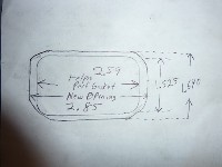
If you did,,I think the port window might look as small as this.
http://img223.imageshack.us/i/p1010123gs8.jpg/ ,which I think is really too small, maybe not on a 194 CI engine.
Just my thoughts also.
MBHD
Hank, yes it was naturally aspirated. At that time, his engine made the most HP per cubic inch(2.14 HP/CI) of any N/A inline in professional competition at 535HP out of just 250 CID. The intake ports were in no way stock in size, it was a full tilt 320+ CFM head from Sissell from his peak time in his career, prior to his passing. So if you can picture the head Kirby has of ours that you've mentioned before, just think of the floor being ground out to the point of it being before you put the brass in it, and stick in a divider full depth. I know a racer currently that I have been trying to get some pics from, that is using this same technique, but has welded the divider in place. Of course, nothing is easy, you have to open to ports up, and im sure they are doing other trick things, but he is being vague in some areas, because it is still kinda' secretive to most of them that use it. But from what Darren told me he did 10 years ago, it ain't rocket science if he did it. He just took some tin snips and formed some dividers to tack weld to his header flange, and he saw a pretty big gain from doing just that. But like anything else, some amount of tweaking or R&D, might be needed to evaluate fully the best overall shape or style to make the dividers and ports.
But don't anyone get ahead of me here. I have always been Pro-lumps, either bolt-in or weld-in, because I have a pretty long background with that technology. But if you want to know what works, just look at what the top guy's are running and setting records with right now. There must be something to it, or they wouldn't be doing it, because they race to win, and if it doesn't win, they don't use it. If I can get some pics, i'll gladly put them on here so we all can give it a try.
No I did not use lumps in the intake.
A port 1" wide by 2" tall has a cross section of 2 sq. in.,
2 sq. in. port will support a :
230 @ 7000 RPM
250 @ 6400 RPM
292 @ 5500 RPM
after this RPM the port will go sonic and VE will drop.
this is a rule of thumb, you really need to measure the air speed
to know what it is, you do not want to go over .6 mach
Harry
Harry, how thick is the divider you are using.
About 1/4 then widens out for the head bolt area.
Harry
Ok, im doing a brazed head now that is 2.625" wide, by 1.625" tall, and was just curious as to how thick you were making the divider piece.
There is a fix for this head...
it just happens to have 4 valve/cylinder....

and GM made it until 1 year ago....
REAL MEN USE PUSHRODS !!!
Just kidding, just kidding
I only wish GM would have kept the original design that Falconer has now. With chevy bell housing etc. But multi
valve heads are the future, anyone just starting out would be nuts to start with anything less.
What's Ironic is back in 1963 when I started the 250/ 292 style had just came out and I thought why are guys still using the old style 235/261 engines now I know.
Anyway as long as it's an INLINE It's cool.
Harry
I dont think GM is doing too bad with there 2 valve heads.
Stock corvette heads flowing 360 -380 cfm
Edelbrock is comming out w/newer replacement heads that will bolt on LS1, LS2 & LS3 blocks & will flow over 400 CFM
All pro LS heads been flowing over 400 + cfm 2 valve head.
4,5,& 6 head bolt pattern.
Look @ the new Corvette run a 10.7 all stock
http://www.youtube.com/watch?v=woOqqfGtqHo&feature=player_embeddedMBHD
Don't get me wrong I am the biggest small block chevy fan there can be, but in 54 years of R&D it's not much better than a STOCK 4 valve.
When a toyota 180 cu. in. inline 6 can run 6.2's @ 250 MPH in a full bodied car it makes me think .
Harry
Just some FYI from a friend.
MBHD
Airspeed in the port will be dependent on demand vs' cross sectional area and length. The "Mach" number will vary along the entire port with the density of the fuel air mix and temp.
It is true that going over a certain "Mach" number will take more energy than you get back and at that point you would start to try to slow down the air.
That is why sometimes engines will make more power with a port that is larger that flows no more air than a smaller one however they do become much more camshaft sensitive.
As to the 2 sq. in. port on the respective engines that would depend assuming the same manifold then the camshaft is what will determine the airspeed for each combo.
As you add duration the airspeed at any given RPM will drop in the port. So each one of the displacements with the same port area could have similar velocities at the same
RPM given different cams (larger In the larger engines)
Hank,
Please ask your friend a question for me.
As I understand, that when a port goes sonic you need to keep the intake open longer. Does this mean if you close the intake later you can turn more RPM without going choke and lose any power?
As an example: On a 292 chevy with a 2 sq.in.choke area on the intake port the engine will go "mach" at 5500 RPM.
What additional duration do you want and should the exhaust duration follow this increase ?
In fact using this port area what should the cam specifications be for this engine for max performance, the controlling factor being the intake port?
Also what RPM increase would this allow you?
Thanks Harry
Harry,Turbo6
His reply,
As a general rule any increase in duration on the intake will lower the velocity so you must balance the area of the port relative to the demand (engine size/RPM)
If one starts out with an engine that has a port designed for limited RPM/HP as in the Chevy 6 cylinder it takes a larger than ideal cam to extend the torque curve (at least with stock type heads) to get to the higher HP numbers.
Most engines of these designs will push the torque up the RPM range about 500 or so as you add 7 to 10 deg. but it also depends on the lobe separation as you start to get to a point of having so much overlap that the type and tuning of the intake and exhaust will narrow the range that runs well in.
Any normally aspirated engines possible power output is limited by the cylinder heads ability to get air into the cylinder and of course the block,crank,rods and pistons capacity to hold together.
But even a well designed engine with the wrong tuning cam,carb and or ignition can run like crap.
As to exhaust relative to the intake it comes down to how well the exhaust leaves. Many 4 valve head motors and small engines that have large breathing capacity like motorcycle engines or the air cooled 911 Porsche motors you see cams that have less timing and lift on the exhaust side as they "blow down" very quickly.
On engines like the 6 cyl Chevy a single pattern can sometimes be used to help make a FAT torque curve but at the expense of top end. adding exhaust duration will extend the torque curve but will soften the rise some.
You will have to decide the real RPM range the motor needs to run well in based on weight,gearing,converter/clutch and how you will be using it.
Remember that the cylinder pressure needs to be within an effective range and load/use at the RPM you want it to pull well at. So a camshaft that might work at 5000 RPM with 9 to 1 compression on pump gas will not be the same as one with 15 to 1 compression even at the same RPM.
The standard for race engines is as much compression as the fuel can take and cam to make the highest torque within the range it runs the most.
Use the lobe separation for width of the powerband (wider will make less peak torque over a broader range) The intake duration and lobe center to tune the peak torque RPM and exhaust duration for over-rev peak HP
MBHD
MBHD,
Thank your friend for the information I really appreciate the help. The lobe separation is what I was thinking about but did not know how much duration to add, and how much it would change the power band.
Harry
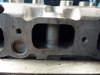
On my Bridgeport now, there is a head getting the intake port widened and the roof raised. Over 1/4" wider and 3/16 taller to start. Not going into water either. Next, a nicer port divider will be made. This head is planned to be tested on the dyno 250, I also have a divided intake that could be tested.
Velocity should still be good as the individual port will not be too small or too large. May get pic's on Sunday. Tom
Here are the pic's, remember this is still on the Mill and not been dressed up (at all). Raised the roof and broadened the sides. Next a bolt in port divider will be made. Any ideas on how to mount it?
If the divider is 1/8" thick the ports will be 1.3625 wide X 1.64 tall, giving a 2.2345 sq in opening. What will the port velocity be then?
Mount in some way that I mounted my upper lumps.
An outside bolt through the top of the port where you install your pipe plugs.
Short bolt w/a location pin.
You do not need the devider plate to be just a flat piece of plate aluminum or steel,you can have a little extra material towards the top of the port for mounting a bolt to install.
It does not hurt airflow to have a little bubble of material extra for the a mounting bolt or some type of fastener.
Hope that makes sense.
Port velosity will go up w/the devider, but I think you will find the cfm will go down,because now you will only be flowing from one port instead from the two w/out the devider.
Also you do notice there is not much material left for sealing.
I had opened up my intake port larger than yours is w/even less material for sealing the intake manifold,& it still did not flow that great & was not practicle for me to run it that way for a street car.
MBHD
Tom,
Back in the 60's I had bolt in dividers, and they were held in by the pipe plug at the top. I made a washer about 3/16 thick with a slot in the bottom of it to hold the divider, it went in first then the pipe plug. But my dividers had a wing shape that flared out, back in the bowl area and this helped to hold it in place, the pipe plug and washer just kept it from falling over, worked very good.
As far as air speed I need more info:
cfm@28"
cam lift
cross section area
Mach index:
bore
valve dia.
RPM
stroke
cam lift
cfm@28"
cross section area
Choke point from RPM:
RPM
bore
stroke
Max RPM from cross section area:
cross section area
bore stroke
Example: your cross section area will support a 292 to 5900 RPM and a 250 to 7000 RPM both with 4" bore and stock stroke.
Good Luck
Harry
Example: your cross section area will support a 292 to 5900 RPM and a 250 to 7000 RPM both with 4" bore and stock stroke.
Good Luck
Harry
Those #'s from your cross section seem about right for most any of either size engine you would want to test within reason.
Chopped up a cracked "194" head. Making the new port plates fit this head and then modify the runner head. Will run the divided head with both a standard intake and a divided intake.
No lumps will be installed. Tom
Cool,
by stateing standard intake & divided intake,what intake manifold ,cast iron 1 barrel?
MBHD
Standard intake will be a Offy and clifford, meaning not divided. For divided intakes , have a Clifford and a as cast Brazilian intake.

Tom, I thought you sold that Brazilian intake, do you have another one? What is the dimension from head intake surace to outside of carb flange in the center of the manifold ?
Harry
He also has their web intake which came from Mrhotrod6.Which another guy bought and had drop shipped to him.For his 250 testing.
Yep , mentioned that in the 250 dyno posts already. That is not a divided intake though.
The Guy that bought it deserves all the credit for getting it to me. He is reaching out to help from New Zealand. Tom
Harry, PM me or give me a call. Tom
Tom, glad to see you are going to use a divided runner intake on some of your dyno tests. Years back I had a '66 chevy truck with a 292 and 4 speed that I installed an Edelbrock SP2P intake manifold on. It was advertised as a fuel mileage manifold but the increase in low and low midrange torque was noticeable and the fuel mileage improved also. The engine was stock except for a split exhaust manifold and the Edelbrock manifold was set up to use the stock 1bbl carb. I'll be interested to see how the Brazilian manifold works with your port dividers.
Gordy
Well is anything new on the intake port dividers.
Man. I just read the second page of this and my lack of knowledge depresses me.
Snowman, don't give up a TURBO more than makes up for all of this BS.
Cracked my Brazilian head but it did't work any better than my stock divided head so I'm back to one of these, until I get my 12 port from Mike Kirby.
St.Louis area lost it's track anyway so I put my street tires back on for this summer, too busy to travel this year anyway.
Did run a 9.61, last run last day track was open this past October.
Good Luck
Harry
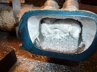
Here is a couple pics of the newer divider. The engine runs much better.
Better starting
better idling
better acceleration
Less fuel needed.
Interesting.
Are you going to dyno or track test it to see the improvements?
See where the torque peak is max HP RPM etc?
No more lumps?
MBHD
Hank,
This head was installed last year in May 2010. I documented it in my 292 turbo writeup. Just posted this here to help keep the data in one place.
Short story. Last year took it to the track and ran it. It performed the same but had power loss. Found out days later the distributor was the problem. So no proven track times.
No lumps because of the turbo and the smaller port window. It does make more power but no dyno close by or time to do it.
The storm that hit me this year was a summer wrecker. Missed out on a week of vacation to cleanup the mess and rebuild my blown down building (just like it was done by the big bad wolf to the piggies). New building is up but much to do to get ready for winter.
Tom, I don't know what I'm looking at in the second picture.
Tom,
Are you planning to sell the divider or is it so custom that wouldn't be possible?
As a pro-lurker here due to my work's firewall preventing me from leaving posts, I just want to say thanks Tom for posting up pictures and updates on the EFI turbo projects. I keep watch as I start working on my turbo'd EFI Pontiac OHC six.
That sounds like a pretty cool and unique project, make sure you give us some pics and updates more often.
Beater,
The second pic is my intake manifold after I matched it to the new head port.
Copo Rat,
Yes those same type dividers can be done, but the head has to come here. Too much fitting.
Silver Buick,
Thanks for the pat on the back. Just trying to keep good info out there for other people to use. Today recieved a phone call. Guy has a 292 that is turboed and making way too much boost. He wants 5-7 and is seeing 14 psi by 4K rpm. He is getting scared of hurting it. We discussed his whole motor and I gave him some ideas on how to calm it down. Ultimately ,I think his turbo has too small of a exhaust housing for his exhaust wheel. He has a Garret 3788 with a .89 exh housing. Just trying to tell him from my experience.
Glad to see you are giving advise.
So Tom,
from your experience, you have used a larger .99A/R, or 1.11 A/R on your 292? If so, how did it work out w/your converter? What RPM did your 292 see full boost w/the .99 A/R or the 1.11? Or better yet, what RPM did your 292 begin seeing boost?

I am interested in your findings.
I believe those are the next 2 sizes available for him to use.
IIRC, off the top of my head, you were using a .68 A/R initially on your 292 & now you currently have a .84A/R ?
MBHD
Never used a housing that big on mine. You are right , have a .84 currently.
His is making too much boost and thats why he called me. I did not sell him his parts , but am trying to help him figure it out.
Yes , when I looked up his turbo, those are the next sizes. They seem to only offer 1 exh wheel. I am used to Turbonetics, they offer different wheels and housings.
What do you think his problem is?
He has timing pulled out with boost
A working wastegate
builds boost quickly
using a blow thru carb setup
water/ alc injection
This stuff is only going to detract from the original post.
It's hard to say what is wrong w/not knowing his layout on the plumbing,what controls the wastegate, parts used etc. & just by talking to the guy on the phone.
"The GT3788R is perfect for 2.0L - 5.0L engines looking to make 440 - 675 HP. Twin scroll T4 turbine housing makes for quick spool up." Taken from a website.
Maybe he could join here & post some pics?
I believe he has the devided/Twin scroll T4 turbine inlet?
If so, he could use the open type, not devided T4 turbine housing.
That should slow it down a bit.
We need to see some pics, maybe some data logs.
MBHD
Turbo too big for only 7 psi it's at the bottom of the efficiency islands. Best suited for 15 psi plus.
What size wastegate ?
What wastegate control ?
Should start a new post.
Harry
Copo-rat,
Dividers are easy to make just cut a cardboard template that fits the port and cut out a piece of steel held in by a bolt or tapered plug in the top of the bolt boss, I have been dividing ports since about 1965, used cast iron crank counter weights furnace brazed in to use the stock bolt, cut steel flat plates bolted in, cast steel wing shaped dividers that bolt in, the same cast wing that goes behind the stock boss that is tacked welded and epoxied in place, all work just fine.
Tom, Very innovative idea of opening the top of the port, have you tried to see what the flow is, how thick do you think the port is afterwards, you should sonic test it. How wide is it at the top now that it's ported ?
Harry
Post number 41801
"Best thing to do is widen & raise the roof of the intake ports."
I did this many years ago that is why I suggested doing it.
The casting is still plenty thick.
I even ported my intake openings more than Tlows.
MBHD
Hank, How do I find this post (41801) do you have pictures?
How do you raise the roof there is not much area to seal now?
Harry
Harry, heres a typical brazed lump port showing how high and wide the ports are generally opened up. This port shown here is a commonly sized intake port with dimensions of 2.540"L x 1.625"H and theres is no telling how many dozens if not hundreds were done this way by Headrick, Sissell and Self and yielded outstanding results.

CNC,
That's a normal lump port, I had one from Kay years ago,but Tom's has the port opened up way more at the top and I did not know there was that much meat to do that safely. I have an old junk head I am going to cut up and see what's there in thickness.
I feel with a Turbo and divided port you need volume more than shape, yes-no ?
I'm just trying to see how much HP I can get from a stock divided head on gas, before switching to a Kirby 12 port.
At about 760 HP now hopeing for more.
Harry
Harry,
I did not take any pics of the intake port after I devided it & raised & widened the port.
You are correct about not much sealing area after opening it up this much.
If you really want to see what a stock head can do w/a turbo & deviders installed.
You would really need to braze the top of the port.
Raise the roof as much as possible & widen the port.
With a turbo & devided port, you should not be so concerned w/intake port volume, you need to concentrate more on how big you can make the intake port window.
Having a better short turn radius helps, but if you are looking to make a lot more power w/your turbo & deviders, focus on the
smallest area of the intake port (basically @ the mating surface area on the cyl head to your intake manifold)
IMO, we do not have a lot of options when it comes to having a good flowing cyl head when running deviders also. Those two things usually does not go hand in hand.
Thankfully you have a turbo that will force the air/fuel into the cylinder head even w/the deviders & having horible flow numbers because the the devider & no lumps.
I was always concerned with intake port velocity when being naturally aspirated, need decent port velocity to make any type of bottom end torque.
But when you are forced induction, worrying about port velocity is not a concern, throw that type of thinking out the window.
Just make the smallest portion of you intake port as big as possible w/out going too crazy (less reliable, sealing issues etc)
I believe you can make more power this way than if you are running a small port w/deviders & lumps. (only forced induction I'm saying)
MBHD
I can send you some photo's of the heads side profile if you want them.Larger then what is on my web site.
So kind of bringing this up from the grave
But Tom
1. Are you still running your deviders
2. How are you holding them in and how is it working?
I have mine made just no idea how to keep them in well I have and idea just would line to know how you were doing it
Or anyone else for that matter it's the last step before wiring on my turboed 292 and custome intake and fuel injection
Thanks,
Josh
Happy inlinning
Josh, there are many ways to do it, and all of them good and acceptable. I saw it done 20 years ago on one of our customers race engines, he simply tack welded them to the end of the intake flanges as an extension that basically inserted into the ports when he bolted the intake on. You could also make a thin spacer to go between the head and intake with them welded to it. Downside may be having to use longer bolts and a spacer on the header flange also, but they stay in place when you remove the intake. You can even use the short head bolt hex cutout as a bottom support and the pipe plug that fills the upper part of the head bolt hole to capture the divider also. Many ways to get there and all are pretty easy. Just pick what suits you the best.
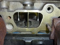
Josh,
Here is how mine are made. First of all, they were made by a fellow inliner and installed by him. He is local to me. At the time there was a bunch of work being done with the dyno engines and he offered to help out.
There is a special plug that has a thru bolt to thread into a nut welded into the divider. The divider sandwiches the head with the bolt and plug.
The engine ran much better once the lumps were put in. Smoother idle and cleaner acceleration.
Notice the lack of lumps and the enlargement of the port. The intake manifold also had to be opened up to match.


Would it be too restricting for a turboed application to not open the port that much?
Very clever idea! How did you seal those on the head?
Not really for a street engine. Im helping a local LS racer that competes in the drag radial class in NMCA and is making close to 1500 HP with heads that are not even ported very aggresively at only 300 CFM. Don't get sucked into the "how much does it flow" hype, its only part of the equation. But I would try to regain the area taken up by the width of the divider in each port. Forced induction is a great compensator and equalizer in making an engine that can't into one that can.LOL
Excellent that makes me feel better about it


