Great work! Nice pics also, as they say pics are worth a thousand words.
MBHD
Tom, I think in all fairness of testing, we have seen that both Hank and Larry have brought up valid points regarding the closed chamber heads, in that they seem to be of the opinion, that with this chamber design, a 1.84" valve, and not a 1.94" seem to yield a better combo, as opposed to a 1.94" valve in a large chamber head or small chamber one, is this correct Hank or Larry. And if so, then maybe to exhaust all efforts to try to either confirm or dismiss this claim, we should throw one of those heads into the mix of testing for the 250 engine, just to say we did explore that claim, so we also can say we didn't overlook the possibility that there might be something to it. And if we still see that the 1.94" large chamber head still shows superior HP and torque gains over the 1.84" valve closed chamber head, then we can in all fairness say that we see no benefits to the closed chamber heads at all, having seen conclusively there is no gain potential with the closed chamber head.
I will also say that there was at least one pair of head comparisons we did try, that we knew beyond a shadow of a doubt that one head had a tremendous flow gain over the other, and we saw ZERO HP gain whatsoever between the 2 heads. One head was bone stock with the bolt bosses still it the head, the other head was the same style head with the same size valves and had lumps installed....so never base expectations solely on flow readings. Do you agree Tom that this would be a final test to make the small vs. big chamber head debate a done deal, as far as the small chamber head having any benefits over the big chamber, or do you think we have done enough with this topic.
I can also add, when testing open chamber heads. A 1.84" intake open head was also down on HP and TQ from a 1.94" open chamber head.
Another side note, the "194" head always had less TQ than the open chamber head. And it was properly opened up to be equal the open chamber head. Tom
Then if you did all you can do to the best of your ability,there is no reason for any further testing.
MBHD
My only 2cents is Neither of the heads were unshrouded properly
for a 1.94 valve.Close maybe.So once again my2cent is you did it to the best of your ability.
And i have seen a 2. valve With the Boss still in the head Flow almost as well as a 1.94 valve lump ported head.So once again It has everything to do with the Proper Port work.
I thought we would exhaust all efforts to show and validate the possibility of your claims, so I guess we'll just leave our conclusions where they stand based on our observations already seen, and move on then.
And i have seen a 2. valve With the Boss still in the head Flow almost as well as a 1.94 valve lump ported head.So once again It has everything to do with the Proper Port work.
Do any of these heads still exist that could be used on the dyno. Could you put another one together? Do they need more RPMs that Tom spun the 292 to? Now's the time to drag one out. Beater
I still want to see the flow testing comparision between the 194 head w/1.94" intake valve as the same combo w/the larger chamber head.
Should be quite interesting.
MBHD
Tom said he would have that done, maybe this week. I think he has already posted the flow #'s some time back for the 1.94" big chamber, lump port head.
I have posted up #'s on the 1.84 big chamber head. In fact with more practice got flows over 240 on the intakes.
Expect better than that with the 1.94 and open chamber head though. Will see.
Also got some interesting info: Lumps vs no lumps ( on a dyno, not a flow bench)
Found out the flow bench is only a indicator and does not really let you know how the head will perform.
Still learning.
My only 2cents is Neither of the heads were unshrouded properly
for a 1.94 valve.Close maybe.So once again my2cent is you did it to the best of your ability.
And i have seen a 2. valve With the Boss still in the head Flow almost as well as a 1.94 valve lump ported head.So once again It has everything to do with the Proper Port work.
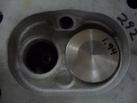
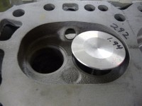
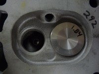
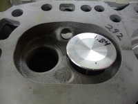
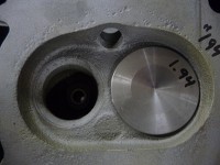
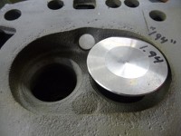
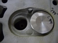
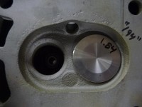
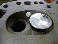
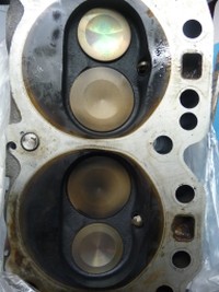
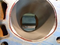
Larry, neither of the heads in the pics have had any unshrouding done to them yet, they are only showing how the stock chambers of each style head is shrouded originally with the respective larger valves that will be put into them, with no work done to them yet.
So, where are the pics after the unshrouding has been done?
What was the purpose of showing stock chambers when there is nothing to compare them with? IE,chambers that have been unshrouded.
The seats or throats have not been cut either,was this a test for something?
MBHD
And i have seen a 2. valve With the Boss still in the head Flow almost as well as a 1.94 valve lump ported head.So once again It has everything to do with the Proper Port work.
Do any of these heads still exist that could be used on the dyno. Could you put another one together? Do they need more RPMs that Tom spun the 292 to? Now's the time to drag one out. Beater
Yes the head is still around It's on a 12 sec camaro (250).Which has been detuned from 11.80s to keep from having to install a roll bar to the car.
So, where are the pics after the unshrouding has been done?
What was the purpose of showing stock chambers when there is nothing to compare them with? IE,chambers that have been unshrouded.
The seats or throats have not been cut either,was this a test for something?
MBHD
Hank,
These pics are taken just for reference. And not the heads used for dyno testing. Simply pics of stock chambers to show how shrouded they are in stock form. Other members of the Inliners club had asked for these.
Most magazines get kinda' cranky when you reveal photos and text in other outlets before they have the opportunity to have the exclusive on them, since they have already been promised to have first dibs on it. A lot of the more over the top stuff is reserved for them....sorry, but you will have to wait for the article(s) to see some of the more story worthy things. In the pics the chambers are shown for reference one to the other, to show how much more shrouded the small chamber is to the large chamber before they are modified, as pointed out in the opening sentences to start with. Also some of your(those that haven't contributed to the project)questions can't and wont be answered at this time without compromising the integrity of the articles, or even the books that are going to be released about these findings, but if I or we can answer anything that wont jeopardize these things, then im sure you will be told. The whole entire purpose of this testing from before it was ever mentioned on here, has always been about putting these findings into the articles, so we have to protect and preserve as much of the data as possible, until its released at the specified times.
I asked for pictures of the stock combustion chambers. I have not seen a stock 194 head identified as such. The pictures of the stock chambers are informative. An yes, realizing that they are the stock chambers is important.
Written communication is always more difficult, and often has more unintended impact than verbal communication.
As most are aware, the stock bathtub combustion chambers are not very efficient. For the last decade or so, two valve combustion chambers have progressed more to the kidney or cardioid shape.
Tom Lowe is making a good attempt to raise the average level of technical competence here for the home mechanic and hot rodder. We, meaning myself and I probably speak for other home mechanics here, realize that some others here have significant experience and hard earned knowledge. We are thankful for those who share this knowledge, especially those who have made an income working with inline 6's who understandably may not feel as free to divulge this information.
1 vote to leave it alone because I am a guy that has my own BS filter. Lee Lites Crank Shaft Data and Photos and Twisted's Head Cut A Ways are some of the best stuff that I have seen on the board. I like to sift and cull through that stuff and apply what I THINK WILL WORK BEST FOR ME combined with my 60 years of experience.I could care less who KNOWS THE MOST. But put it all in a pile with all this DYNO data... DAMN.... thats a bunch of good stuff ... no matter if you are a racer or trying to to get 25 mpg...!!!
I do care if there will be misinformed information passed around here all based on these dyno results which is not the final say all tell all on every combo known to man on what works or does not work.
The dyno sessions will be a good base of info,for an average street engine.
There is a lot more to learn on what works & what does not work w/these cylinder heads. And getting info from one guy from dyno sessions should be taken like a grain of salt.
Not trying to be rude here @ all, I just see the mistakes being done, main one that he cannot even believe himself that you can use a small chamber head & get great results if properly modified, that's is OK,it just shows he is not experienced enough to know what to do or change his ideas of porting ,valve jobbing,and correct chamber unshrounding.
It takes many years of experience to get a good grapse on how airflow works,port shapes & contours with cylinder heads.
I had my daily street driven Camaro when in my 20's run high 13's get 21 mpg on a normally aspirated 250 6 cylinder. I am not proud of running 13's especially for todays fast cars,,but it took a lot of R & D time w/me & my friend that works @ a cylinder head shop for over 25 years.Where I hang out most of my spare time.
My Camaro was never by any means a drag car. It had front & rear anti sway bars,stiff springs,Koni adjustable shocks,,more set up for road racing than drag racing.It also weighed @ the lightest 3000 LBS no driver.
Guys w/Buick Grand Nationals & Turbo T-Types have been running mid 11's w/a turbo swap,injector swap,chip swap,slicks & race gas(back in the day,not pump gas & methanol injection kit, todays standard)on completely stock 3.8 V-6 & still get 18-21 MPG. Full weight 3800 lb cars.
I have seen many get kicked off the track because they had no roll bars, becasue these were there daily driver cars & take them to the track.
If I were to run 13's when my turbocharged EFI 250 CI L6 Camaro is up & running ,I ll quit posting on this forum!!
BTW,the Camaro is & will be a street diven car,,no trailer for my Camaro. Driven to & from tracks.
I'll keep quite for now.
Moderators delete away,if you feel the necessity.
Note:
No PM's will be responded to if it pertains to my post.
I don't need the headaches.
No flame wars either I'm tired of all that mess.
MBHD
I am not bashing you on your effort,for that I commend you,really!
I just get really irritated if someone states,dont use this or dont use that,because on my head, it did not work , this is all being based from one person doing a engine dyno session, so I get irritated, that's the way I am. Sorry.
Fine,,, state it simple, my findings where this & that,it's very irritating when you state don't use the 194 head.
I am not saying the 194 head made less HP or torque w/your findings,not thinking of any conspiracy ideas.
You can state you opinion, that's fine, I will state my opinion also.
Modirators have the final say in it all, & as I stated before,,moderators delete any or all of my postings for bashing.
Thank you.
Or if they don't I wll try & delete them myself if you like.
The only other thing I disagree w/is about the Offy intake,you sate that the Clifford has more power on all your tests,,,well of course it does your tests start @ 3000 RPM,where the Clifford is supposed to make more power @.
Not everyone drives around town @ 3000 RPM.
It is from idle to 2500 or so RPM is where the Offy will out torque the Clifford. This will be especially true & felt more on 250 CI engines & smaller
MBHD
Now as one other note. I have to agree with Hank as to the Offey
and clifford Issue.I have ran both intakes ON and off the street.For me personaly and MY! motor combo at that time. a crane
RV cam Headers Other then that it was a Bone stock motor. And a
600 holley (stock out of the box) was used. The Offey felt and
performed the best.
Tom as to what your doing I'm noy bashing in anyway shape or
form.To many vary's (tuning,push rods. rocker issues,so on)Lack
of time, money.
The debate is healthy, the squabling is normal human nature, the scenery is great. Keep up the good work Tom, and thanks.
S
I am only paid up until 2014
The best thing that comes from all of this will be for more guys to build more engines and prove each other wrong, that we can all learn from that.
Go ahead and post drag strip numbers or dyno numbers or even fuel mileage, we don't care, just don't stand there and tell me your crap is better then my crap. I can go to any local cruise night and hear that!
Here I will start, stock 250, home made intake with three Corvair carbs, stock exhaust, stock cam, 3100 lb 1937 Chevy truck, ran 17.91@ 74 mph. Thats little over 140 hp at the flywheel and about 125 or on the ground, There I feel better!
The dyno is no way the ultimate answer, its purpose is to show the difference between parts on the day they are tested, same for a chassis dyno, and as stated before this started, dyno's don't work right below about 2500 rpm, 3000 is even better. Depending on the dyno set up, and there are a lot of them, you can make a engine perform as you want. I seen my uncles car gain 15 hp on the chassis dyno, just by airing up the tires , so did the air add HP to the engine? I doubt it.
There are so many ways to one job, it would take a years worth of dyno test to prove anything 100% true. So go build that engine and slap it on a dyno or in a chassis and show me.
Joe
If i missed any that maybe should be pulled from here yet Please let me know. If i pulled any that should have been left sorry.
Beater and other guy's,
Take it easy, I asked Larry to delete the posts that took away from our goal here on INLINERS. Tom
Thanks Larry!
Now lets all cool down and keep the inline stuff coming!
Yeah you do too care Beater, so come on. We were all starting to get a little of course on this one, so now, we have all said our piece and lets get back to making some more HP. We have all gotten past this, so lets move forward, and keep up the good work, its all about teamwork.
Can we just lock this and move on?
I don't think there is a need to lock it out at this time,Beater
I only tried to remove what seemed to have to much conflick/BS
in it.And not much of anything to due with the topic ay hand.So
like i said sorry if I removed more then what wasn't usefull. To
the topic at hand.
Your bud is the deleter he did mine. You spew venom and tell me to relax? When the two of you changed the "topic" of this thread to your vast experience and expertise verses Tom's test results it became another discussion altogether. I defy anyone to find a post by me that is as disrespectful as those by you and Larry on this thread that were left and have nothing to do with valve size or Tom's pictures. I don't mind difference of opinion, or even a ruckus but I truly have a problem with selective censorship has no purpose except protect fragile egos and exert control. I really expected a fair exchange here but I guess I was mistaken. I now understand why so many leave this board and Inliners also. Where's the free exchange? Now it's said and I am done with this, Probably Tom
Ok i only removed what was asked Or at least tried to clean it all up.So now Enough is enough??? So either it can get Back On topic Or We can remove the whole thing and start Over. What is it going to BE?? It will be as simple as that.
Tom also remove the web link (your web link)It can stay in your profile But remove it from Post topic replies.
I'm Good. Lets talk about valves and stuff. Would a 2.0 valve even fit in the small chamber without unshrouding?
Tom If you do not remove your web link it will be removed for you.Thank you
I'm Good. Lets talk about valves and stuff. Would a 2.0 valve even fit in the small chamber without unshrouding?
Take a look @ this ,it is a 1.94" valve
http://img215.imageshack.us/i/194194open.jpg/http://img80.imageshack.us/i/194194.jpg/
Yep, just wondering what it would looks like before you start to unshroud it. From there you are limited by the bore size? Is the shape from the top of the cylinder to the valve seat part of the magic or is it simply careful metal removal? Is the real trick on the back/port side of the valve? Beater
I would think Twisted6 has some good pics of a properly unshrouded chamber.
MBHD
Do you think he'd share them? From the chamber side would you want a different shape on the intake and exhaust since one flows in and the other out? I've never done any serious head work.
Do you think he'd share them? From the chamber side would you want a different shape on the intake and exhaust since one flows in and the other out? I've never done any serious head work.
Just go to his profile and click his shop link. Lots of pics there and maybe something of interest or help to you.
Here are a couple pics of my cylinder head.
The 71 cc chamber has been laid farther back to increase the airflow. They were @ 65 cc" IIRC.
The other pic,chamber has not been opened up yet.
Just don't go past where the head gasket seals to the block.
Use blue dykum (SP) @ scribe a line where the head gasket edge is.
Don't get too carried away,,but his will give you an idea how to correctly get more airflow by laying the chamber wall back.


MBHD
Nice picture Hank. Who manufactured the base head? The spark plug is not in the same location as the stock head. It has been moved over to the exhaust valve side to allow more unschrouding around the intake valve, a modern design.
Wow, That looks good! Not much room between the valves. 1.94-2.0 & 1.60? The outer intake edge is to the gasket sealing surface? And as Winter says the spark plug hole relocated. That is serious work. Thanks, Beater
The head is my Kirby/Sissell aluminum head.
The valves are 2.08' in & 1.65" ex IIRC.
It is a work in progress still. It flows about 320 CFM @ .600
It would flow a lot more if I opened up the intake port,but it is a street car & not a max effort all out performance head.
The intake is 1.71" round port.
Mike has got to 400 CFM on his all out ported bigger valve set-up head.
The cylinder head is pretty heavy (still lighter than stock cast iron head)& has a 3/4" thick deck suface
MBHD
OK, that explains a lot. Those are all big numbers. How much clearance is there between the valves? I bet that number is a small one. It still runs a stock size head gasket? Did you have to relieve the top of the cylinder for valve clearance or do they not open that far even @.600? What kind of rocker set up does it use? Beater
Cant remember the clearance between the valves but there is a good margin.
The valves are spaced further apart than a stock head.
Mike Kirby's race head uses 2.11 intake valves. Same as my head but bigger valves & a lot more porting.
Stock head gasket fits.
Did not need to relieve the top of the cylinder ,but I am thinking I will do so to futher improve airflow. Like BBC's
I was hoping to run a shaft mounted Jessel set-up but the valve cover is too close to the rocker arm mounts,& valve cover would be too close.
I would have to modify it for a Jessel set-up to work.
It would be cool to do so but probably not be worth the time or money.
So I will use standard BBC roller rocker arm set-up for now. It will work just fine.
In the ports where the guide boss has been smoothed a point is left on the back side. Does that aid in flow?
Yes it does improve airflow,plus you can angle it a bit to change direction of airflow. But normally you keep it pretty much straight.
Are you planning on porting your cylinder head?
MBHD
Yes, But nothing too radical. I'm just building a good turboed truck engine. A hay hauling trailer puller. Bigger valves, lumps, and enough grinding to make them fit.
I looked at Larry's cut aways again last night. When installing the lumps does the new short allen head pass completely through the lump? The bolts for my PES lumps don't. Do you wait until the lumps are in place to enlarge the hole? Do that when you counter sink? How far do you counter sink into the old bolt boss? 1/8" ? Beater
The reason PES's do not pass through the lump is Poor Quality in the casting. If you could look at a set of PES's you would see the shift/off set in the casting,So the bolts do not fit.When the boss has been Milled!! out the right way!!!! There should be very little to NO boss left behind. Then you blend off the rest of it. Then you can Respot face off the floor.Once the cutter has made a full circle cut you are done. The is no Need to counter sink the New allen head bolt.
So when installing a set of PES lumps you can either Open the hole up before hand Or after they have been bolted in. Either way
just be sure you have clearance around the Head bolt before you
do the final install.
Thanks! In your opinion, and I think I know the answer here, Is there any advantage to raising the intake floor to use the PES lumps as the were originally designed or round them to match the manifold? Didn't I read here that even leelites talked of reshaping the front edge? I guess I'm asking if the newer shape is for performance, ease of installation, or really makes little or no difference. And yes, There is a certain crudeness to the PES casting. Thanks, Beater
Beater, I think LeeLites is still lurking around here. He apparently has been watching this post and others, and I think he has called Tom a few times about this dyno testing. From some of the comments he has made on his auctions regarding the PES lumps, and how they should be installed. He had mentioned several times on these auctions and claimed, the PES still had superior flow even when ground and formed into a teardrop shape at the leading edge, compared to other lumps currently on the market. But also commented, that how much more would they flow when used in the manner in which they were originally designed, with the straight squared off leading edge, and an insert or ramp placed into the floor of the intake manifold. Well, we wanted to know as well, so we tested all 3 brands of lumps in the same cylinder head, just so that debate of one head being prepped or biased differently than the other wouldn't arise, and discovered that all 3 brands produced the exact same HP and torque #'s one to the other. Tom even went as far as to make and use the ramps in the intake manifold on the PES, just so that doubt or question could be eliminated from further debate also. So the bottom line is likely going to just fall onto it being more a preference issue than anything else as to which ones to buy or use. The very first dyno test that was conducted was with a bone stock head w/1.72" intake valves, and still had the bolt bosses in the head. Then the same head was swapped using 1.72" valves also, but also had lumps installed. We knowingly had a 40-50 CFM gain in head flow from doing this, but the engine didn't make a single bit more HP or torque whatsoever, not even 1 HP at all, so don't expect that if you do have just a few scant CFM difference in a head to see a miraculous gain of HP either, airflow just doesn't work that way, and if you do get a gain in HP, it isn't a proportional gain by any stretch of the imagination either.
Also as a side note These where HIS controled limited tests and Not much time for proper tuning. (carbs, intakes, timming,exhaust)but good for a base line for any bolt-on build.Like Tom said he had issues with PES intake. again a Tunning issue.So he seen no gains in performance.But also that intake was not designed as a Low Rpm performance.But if it was tuned right It Mite be fine for someone.
I don,t think all the tuning,porting,lumps,large valves, in the world would flow that PES intake through these stock designed heads. That thing is a BEAST !!!
It's like Twisted says,"good for base line for any bolt-on build" What Tom has done has compared lots of combos on the same short block on the same dyno in a short time. We all know that any one of those combos might be maximized to better results. Also that in some cases higher RPMs might have favored some of the equipment. Some of the results are interesting such as the stock valve size not doing better with bosses removed and lumps. Does that mean the stock ports will flow all the valves will handle? Does the CFM increase with stock valves and lumps but no gain in torque or HP? Are there flow bench #s for this. What size valve begin to show gains, 1.84? Is there more to learn about the intake vs. exhaust ratio. is getting spent gasses out more important that we think? The more we learn the more questions there are. And I agree about the PES manifold it is definitely not a restriction! Velocity killer maybe. Beater
The runner ports are not all the big.At the head they are fairly small. How ever the runner does open up in size after the bend to
the head. Once past the head part of the runner going up to the
carb they are some what larger. But i do not think much larger
then any clifford.The pes intake was designed for a Large carb
and to be leaned out for it to run right.
By big carb do you mean 650-750 cfm? From the carb do the runners get smaller as the go to the port? When it passes into the head does the port have more or less volume than the runner? Beater
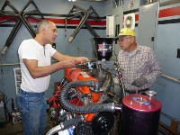
Her is a pic of 2 guy's having one great time. Can anyone name them?
The PES intake is pictured. It will accept a standard Holley carb bolted directly to it. The runners are smaller than a Clifford, but are much more of a direct shot to the carb. The port entry to the head is short compared to a Clifford.
Larry is correct, they like less jetting. We will try this again on the 250 dyno tests.
Larry, do you want to prep a "194" head to be tested on the 250? I would certainly run it. Or even a open chamber head?
Or anyone else?
Here is a neat article about relying on flow bench readings. Interesting read.
http://www.rehermorrison.com/blog/?p=275
There was or is another article out there pretty much just like that one and I have read both a few years ago. And they are right.And yeah Tom Langdon on the right and the saw guy on the left.lol
I know nothing about performing a dyno test. Why is necessary to have such a large air horn on the carb?
"The Saw Guy" now thats funny I don't care who you are! Tom, I think you have a new handle. That's like calling Truman "Margaret's Dad." Larry cut to the quick with that, pun intended. Always, I mean ALWAYS refer to people by the least of their accomplishments and you'll get a rise and the innuendo is never lost. Thanks Twisted you made my morning.

Sorry Tom but it is funny. Beater
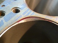
To find out what kind of valve to cylinder clearance we had, I did a little experiment. I cut a 3 7/8th inch circle from construction board and centered it over a cylinder on the block. Using a ball peen hammer, the head bolts holes were cut out. This was laid over the head and the area where the cylinder head overlapped the block was marked with whiteout. 1.94 intake and 1.625 exhaust valves were put in @ 1/2 inch lift. As you can see, a 1/16th drill bit would not fit between the valve and the cylinder. a 5/64th bit would just fit on the exhaust side.
This is shrouding!

Armond, how far apart are the axis of the valve centerlines and the cylinder bore centerlines?
To experienced others:
Is this alignment typical of the 230/250/292 engines? Can the bores for the cylinder head bolts be elongated some for better alignment by shifting the cylinder head, bringing the cylinder head down relative to the construction paper bore (as shown in the photo)? This would allow better combustion chamber shaping also.
The best method for chamber shaping and relieving, should involve placing the cylinder head onto the blocks deck surface, and then securing it with a couple of head bolts. Then flip the block upside down, and reaching down the cylinders, scribe the cylinders outline onto the heads deck surface. Once the head is removed, you can unshroud the chamber to this point around the valves as needed to further enhance its breathing. This method will guarantee that each chamber is unshrouded to each specific cylinder it will interact with regardless of any core shift in either the block or the head. Elongating the bolt holes wont allow the head to move, because it has dowels that locate it.
If you look very closely at the picture, you can see the scribe mark I made by placing the head on the block and scribing the head. This is where the cylinders mate with the head. Moving the head over 5/16th on the block would center the valves and combustion chamber. It seems like a lot of work to get every thing to match up (dowels, push rods, water holes).
That's a good point about the dowels, I would prefer to retain some sort of positive location on the head if I were playing with that, so I wouldn't want to omit them from a runnable engine.
However, if one were to plug those holes and re-drill them elsewhere, AAANNND deal with pushrod clearance is it possible to move the head over the 3/8" or so to center the valves over the bore without spraying water everywhere? (also without welding on the head or block)
I am asking as there appears to be an extra 1/8" of valve to bore clearance if they were centered, that could (maybe) get enough material to unshroud the valves without a bore relief.
Nex, you are absolutely right. Im sure everyone knows that offset head dowels are available for the SBC and BBC engines, as well as others, so im sure there would be benefits to shifting the head to help this problem on these engines. You just need to find a compromise between keeping the additional grinding and clearancing for pushrods and water passages covered to a comfortable "happy medium", so it will be a benefit instead of just an exercise in futility. Im sure it could be helpful to try it, and might even see some surprising results from it.
Many have done this along with milling the head on a angle.
milling/shaving more off the plug side of the head.
To move the head 1/8" would be fairly easy, farther than that lots of things will come into play.
The first 1/8" would involve simple elongating of:
Head bolt holes
push rod holes
Some allining of water and oil drain backs and the dowel pins.
To go farther than a 1/4" will get the cylinder close to the head water passage between pushrods. And the bolt boss in the siamesed port will get thin and close to water.
It may be way easier to just relieve the block. I do have a bad 250 that can be cut up. That way thickness's can be checked at top of cylinders for relieving.
Armond, Nice pic! Good showing of a bad chamber design to go over the block. Tom
Alignment of the cylinder head is a concern for two reasons related to air flow around the intake valve.
1) Centering the valves in the bore will help unshroud the valves around the sides. Centering will also reduce or alleviate the ridge formed by the combustion chamber extending beyond the cylinder wall.
2)The area above the intake valve in the photo (spark plug side of the combustion chamber) is the high flow side of the valve. This area is very important for unshrouding and blending for good air flow. As shown in the photo, the size of this area has been reduced by placing the valve center line above the cylinder bore centers. Positioning the valves centers above the bore center line as has been done is more disadvantageous for good air flow than positioning the valve centers below the bore center line. Relocating the cylinder head on the block would be a pain. Significant performance increase may result, so that's why I asked. And, I agree with the statements above by others on the compromises to be evaluated concerning effort, cost, and performance results.
Larry (Twisted Six), as you stated that this has been performed in the past, do you recall the performance results of centering the cylinder head in the cylinder bore?
1/4" is the practical "easy" limit?
Good to know, thank you all.
I thought maybe I was seeing things, again.
Winter, we also experimented with moving to cylinder head around on the deck surface. We did see some negligable gains, but found that just unshrouding the chamber was the best and most effective way to get bigger gains. I know of several top Comp Eliminator racers that today currently have even moved the intake valve centerlines away from the bore toward the exhaust valve, and have gotten the same results as if they unshrouded the chamber with the valve in the stock location. They are currently using a 21 cc chamber that was been completely redesigned and reshaped. Also long gone are the familiar lump style intake ports, this has been abandoned almost 10 years ago by most all of the top frontrunners still using the siamese heads in professional racing, in favor of more modern technologies, and are experiencing intake ports with flow #'s over 400 CFM. Thats pretty amazing, since the Ford guys are allowed to use the AJ Billet head for their engines, and thats about the same flow #'s they are getting from them, so its pretty cool, that a 30+ year old head casting can perform closely to a state of the art billet head. I think you can see that even the chamber itself still needs to be unshrouded when using big valves, and that just moving the head around by itself doesn't eliminate or correct that, it only corrects the cylinder shrouding which is a different issue. When using a 2.150" intake valve as we did, you have to notch the top of the cylinder to unshroud it. It also is helpful to do this on smaller valves also, especially if you don't have a big cylinder overbore.
CNC-Dude, thanks for the information. Are your references of examples specifically from Chevrolet 194/230/250/292 cylinder heads (except for the Ford head comment) or for other type cylinder heads as well?
Winter, yes this info is specifically for the siamese port heads only.
Scott - In response to your post, having been out of NHRA racing for several years, I wasn't aware that there were any competitive Chevy siamese port Comp Eliminator teams still participating. Could you let me know who these teams are, especially the one producing air flow numbers over 400 cfm. I'd like to contact them to get some technical information on their cylinder heads.
Thanks,
Bob
Your right, there are very few currently still using the siamese headed engines. Its doubtful they will even discuss it with you because the world of Comp and most Pro classes is very secretive, just like Nascar or any other class that relys on speed secrets to gain an edge.
Scott do you think those guys use a surface model for combustion chamber geometry and is touching up the combustion chamber with a ball mill something not even they would bother with? In my world Im only firing on all cylinders when handwork has been reduced to zero and unshrouding/chamber shaping are going to be requirements in the older head so this topic relates well. Has anyone tried a helical trench, bulge, or other geometry on the tight side rather than just blending up to a scribe mark and/or automated the shaping process for consistency and finish? I would have thought that proven chamber designs would be out there with the huge following behind these engines.

Finally got #'s back from the flow bench testing of the 2 different heads being discussed. Both heads have the same amount of machining, porting, HI-FLOW lumps and valve sizes being 1.94/ 1.60. Both heads also had a cutter used to remove material in the chamber to give appr .150 clearance to the chamber wall.
1st head is the "194" head.
Lift Flow CFM
.100 59.4
.200 117.8
.300 161.9
.400 192
.500 213.9
.600 227.3
This is the open chamber head

Lift Flow
.100 60.9
.200 118.6
.300 176.5
.400 211
.500 231.8
.600 246.1
As can be seen here , the open chamber head clearly outflowed the closed chamber head with the same modifications done. If someone were to spend countless hours opening the chamber on the "194" head, then flow would certainly improve. This is not what the average Guy will want to do for a street engine.
When these exact same heads were tested on the dyno 292, the "194" head was down on power compared to the open chamber head. Even with the increase of compression help the "194" head, tq was down across the rpm range.
A 1.84 intake valve could be tried in the "194" head. From prior flow testing and dyno testing of the 1.84 valved open chamber head, also on the 292 mule, power was down and was nearly equal to the 1.94 "194" head.
Tom
I just can only say again,,,you cannot use a 1.94" intake valve in a 194 head,they cannot flow that way,(unless you modify the chamber greatly) you would need to cut down a 1.94" intake to a smaller size to make it work & be a closer/better comparision.
Valve jobbing is very critical,if one seat is .010 wider on one cylinder head, another head being compared to has a narrower seat, you can loose 10-20 cfm just from that alone.It depends on a lot of factors.
Like I said before,you dont learn this stuff overnight,just in a couple hrs is all it takes, sarcasium, again, sorry.
I didnt see it maybe I missed it , just curious on what the head cc'd at for the 292? Im currently building a 292 and we went with 70cc per combustion chamber on the head. any info is greatly appreciated..
The large chamber heads were 70cc.
thanks for the info thats what I went with ..
This is a related subject. I have done this to help flow from the chamber. As Armond has pointed out in a earlier post. The chamber overhangs the cylinder in these engines with a open chamber head. Chamfering of the chambers was done by me to help with this condition.
Tom,
Since it looks like the small "194cid" chamber was restricting intake flow, I wondered, did you compare exhaust flow for say a 1.60 exhaust valve with some port work, flowing out of the small "194cid" chamber/exhaust port vs flowing out of the open "292cid" chamber/exhaust port?