|
|
Joined: Dec 2010
Posts: 535
Major Contributor
|
OP

Major Contributor
Joined: Dec 2010
Posts: 535 |
|
|
|
|
|
Joined: Aug 2006
Posts: 153
Contributor
|
|
Contributor
Joined: Aug 2006
Posts: 153 |
Cool project!
What ECM and triggering are you using? Love the LS style coil mounts.
Why not a traditional fuel rail?
|
|
|
|
|
Joined: Apr 2004
Posts: 3,556 Likes: 35
1000 Post Club
|
|
1000 Post Club
Joined: Apr 2004
Posts: 3,556 Likes: 35 |
I like it! Bet it will run great when done. Keep us posted on how the fuel lines terminate to the injector tops.
More pics with progress.
Inliner Member 1716 65 Chevelle Wagon and 41 Hudson Pickup Information and parts www.12bolt.com
|
|
|
|
|
Joined: Dec 2010
Posts: 535
Major Contributor
|
|
OP
Major Contributor
Joined: Dec 2010
Posts: 535 |
I tried answering yesterday but the forum software doesn't like my work or home computers....
I'm going with a MegaSquirt 3, full sequential on fuel and ignition. I have a trigger wheel I'm going to bolt to the harmonic balancer and use either a Ford VR sensor or an aftermarket hall sensor to trigger it. I'm still settling on the cam trigger, either modify the points lobes or I have a few other ideas too. This is version one of the engine, basically throw together parts I have. The next version will be turbo'd and a custom intake and probably custom headers.
I'll update this thread as the forum software allows. It has something to do with the UBBCode.
This is the error I get every time:
The host from which you are accessing the board is not recognized as a valid host. This is more than likely related to a firewall issue that is blocking the referer variable. Check your firewall settings and try again.
|
|
|
|
|
Joined: Dec 2010
Posts: 535
Major Contributor
|
|
OP
Major Contributor
Joined: Dec 2010
Posts: 535 |
Hmm, I just logged out and logged back in and it posted, maybe that'll work for me from here on out.....
|
|
|
|
|
Joined: Dec 2010
Posts: 535
Major Contributor
|
|
OP
Major Contributor
Joined: Dec 2010
Posts: 535 |
Keep us posted on how the fuel lines terminate to the injector tops.
On the Car Craft Anti-Tour last year I ran into some regulars that had a Jeep 4.0L head with EFI on their straight six in a gremlin and used the plastic fuel line from the pump to the fuel rail like a stock application. They said it was real easy to put the line in hot water, slide it on to the fitting, then done. At the parts store I see both 18" patch kits of the plastic line and 3+ feet long rolls of it. So it's readily available.
|
|
|
|
|
Joined: Apr 2010
Posts: 106
Contributor
|
|
Contributor
Joined: Apr 2010
Posts: 106 |
Distributorless eh?? Very cool! I have a pile of 4200 electronics/harnesses etc, and LS Cam and Crank wheels to attempt the same thing on my Chevy 250! Can't wait to see this finished. Keep us posted.
Last edited by copo-rat; 02/12/13 03:34 PM.
".....don't give up a TURBO more than makes up for all of this BS." Turbo-6
|
|
|
|
|
Joined: Dec 2010
Posts: 535
Major Contributor
|
|
OP
Major Contributor
Joined: Dec 2010
Posts: 535 |
Started on proto-typing a cam sensor for the engine. I cut down the top of the distributor shaft and using some of the plexi-glass and I rough cut a cap on top of it. How it looks. I could probably paint the cap black or something and put a Pontiac arrowhead logo on it.  I gutted the mechanical advance stuff, and with the height of the walls I think I can get a relatively cheap and modern cam sensor mounted on the side of the distributor and on the advance plate I can weld on a metal tab for the sensor to pick up.  A sensor like one of these:   Might even look at speed sensors. 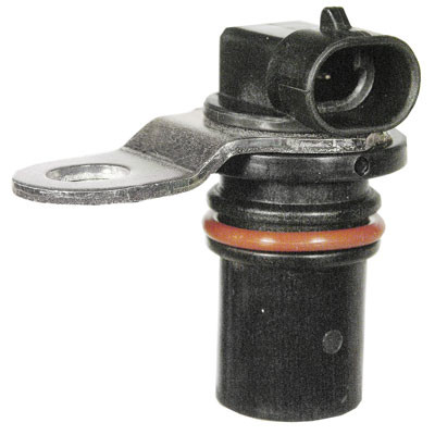 
|
|
|
|
|
Joined: Dec 2010
Posts: 535
Major Contributor
|
|
OP
Major Contributor
Joined: Dec 2010
Posts: 535 |
Last night I finished up the MS3 assembly. Three nights while watching movies or tv.  Here it is with it's clothes missing.  I've finished up two of the intake ports on the injector bungs. I got greedy and tried to do the second set of ports and the JB weld wasn't cured and half way through grinding on one of the bungs it broke loose. So I have to redo the rear two ports and I left the front two alone as I just installed them today. The left one I ground down and the right is unfinished.  With the injectors installed.  And then I made things pretty. Still haven't installed any gaskets so it'll all have to come apart for final assembly. I still need to paint the water pump pulley and the trigger wheel needs some drilling to mount it to the harmonic balancer.  Cleaned up the coils and painted the coil brackets.  Guess I've settled on the paint scheme, lol.  Painted the exhaust manifold as well.  A reminder of what the dual exhaust looks like. Two 2" outlets.  So the final question is, what color do I paint the intake manifold? Pontiac Blue? Red? Aluminum/Silver? 
|
|
|
|
|
Joined: Apr 2004
Posts: 3,556 Likes: 35
1000 Post Club
|
|
1000 Post Club
Joined: Apr 2004
Posts: 3,556 Likes: 35 |
Nice work, looking good.
I'd go with red on the intake. Do you think it will be running this summer?
Inliner Member 1716 65 Chevelle Wagon and 41 Hudson Pickup Information and parts www.12bolt.com
|
|
|
|
|
Joined: Dec 2010
Posts: 535
Major Contributor
|
|
OP
Major Contributor
Joined: Dec 2010
Posts: 535 |
If all goes well I hope to have it running in April. I was shooting for March, but that is becoming quite optimistic given the work the car needs.
I want(ed) to build an engine test stand, but may be foregoing that on time constraints.
Basically what is left in rough order:
Permanently mount the trigger wheel
Finalize the cam sensor
Run the fuel lines on the engine
Finalize Q-jet/Throttle body
Wire up the engine.
Paint the water pump pulley and alternator bracket.
Final assembly on the engine (with gaskets this time)
Pressure check my oil mod (assuming no issues at this point)
Plumb return fuel line and surge canister on car.
Set up two fuel pumps, priming and high pressure.
Clean up engine bay wiring.
Install engine.
Figure out what trans to use and install.
Install exhaust.
Bleed brakes.
Start engine.
Clean up interior of car.
Drive.
Okay its starting to look like May =P
|
|
|
|
|
Joined: Sep 2008
Posts: 3,669 Likes: 42
1000 Post Club
|
|
1000 Post Club
Joined: Sep 2008
Posts: 3,669 Likes: 42 |
Looks good, have you thought about moving the trigger wheel closer toward the engine.
Class III CNC Machinist/Programmer
|
|
|
|
|
Joined: Dec 2010
Posts: 535
Major Contributor
|
|
OP
Major Contributor
Joined: Dec 2010
Posts: 535 |
Unfortunately I can't. I would ideally like it behind the pulleys, but the timing belt cover wouldn't fit over it and it'd require serious cutting of the wheel then welding to the back of the pulleys on the harmonic balancer. And be mindful that this has a pressed on balancer and in the pictures the balancer is just barely hanging on to the crank snout because I didn't want to press it on then pull it off for the picture, so that balancer actually gets quite a bit closer to the timing belt cover. This thing is definitely going to be a saw blade on the front of the engine. I'll make sure to put a "Warning: Don't stick your hand under the fan!" sticker on the core support, lol. Last year I saw a guy that converted an AMC 258 to EFI and had his trigger wheel hanging off the front end just like this (same wheel make even). I know one other car that is set up the same way, the guy calls it the saw, lol. Here is my Skylark's which to me is ideal.  
|
|
|
|
|
Joined: Dec 2010
Posts: 535
Major Contributor
|
|
OP
Major Contributor
Joined: Dec 2010
Posts: 535 |
I thought I wanted a red intake until I had a red intake, lol.  So it got another coating of some Pontiac Blue.  Painted up the water pump pulley and thermostat housing. Started the process of customizing a Q-jet for a throttle body.  I thinking of painting the Q-jet after I get it all cleaned up, but I'm still on the fence about it.  Look Ma, no venturi's!  The worlds cheapest 800+ cfm throttle body.  Tomorrow I'll possibly start on the fuel lines and some wiring. I need to drill and bolt down the trigger wheel and start looking at fabricating up a crank trigger sensor and start making progress again on the cam sensor.
|
|
|
|
|
Joined: Dec 2010
Posts: 535
Major Contributor
|
|
OP
Major Contributor
Joined: Dec 2010
Posts: 535 |
Got back to this yesterday. I finally gasketed the engine, so it's together for the long haul now. The only gasket I did not install was the cam housing gasket as I haven't got to the point of setting the cam timing and triple checking it for the EFI, so it'll be removed a couple times. Also finally got spark plug wires for it and drilled the trigger wheel to bolt to the harmonic balancer. And typical Randal cut twice and it's still too short it took me two tries to get the trigger wheel centered =/ Tomorrow's game plan is to attach the intake and exhaust back on it, plumb in the injector caps and start working on an engine run stand.  A picture with out the cam cover, I'll have to remove the timing belt from the top sprocket because I didn't actually set the cam where it needs to be (plus the cam followers are not installed), but the belt had to be installed since I installed the harmonic balancer for real this time (pressed on).  Also installed an internally regulated alternator, that one is a ~65 amp one, but eventually it'll probably get ~120 amp one. 
|
|
|
|
|
Joined: Feb 2009
Posts: 70
Active BB Member
|
|
Active BB Member
Joined: Feb 2009
Posts: 70 |
Coming together real nice!
Any plans on porting that throttle body? Looks a bit varnished and gummed up.
Alex
|
|
|
|
|
Joined: Sep 2004
Posts: 5,839 Likes: 1
1000 Post Club
|
|
1000 Post Club
Joined: Sep 2004
Posts: 5,839 Likes: 1 |
Looking good!
How's the injector bungs held in place?
MBHD
12 port SDS EFI 
|
|
|
|
|
Joined: Dec 2010
Posts: 535
Major Contributor
|
|
OP
Major Contributor
Joined: Dec 2010
Posts: 535 |
The Q-jet, if I stay with it, will get a through cleaning before actually going into service. As you can see I already gutted the venturi's out of it and 750-800 cfm is already well above what a simple 250cid engine will use, lol. I have a a nice single throttle body that is an aftermarket piece for a Ford and a 90* elbow. I may see about working that in and not using the Q-jet. I'm on the fence at the moment. The bungs are simply JB welded on. I took a grinder to the outside of the injector bungs to give them texture for the JB weld to bite on to. Some more updating. A long while back I removed the back pressure valve that was for warm up, and it left two holes in one of the exhaust outlets. So today I tapped threads into them, slathered some JB Weld onto the bolt threads and ran them into the holes. Then ground down the threads flush with the sides.   Installed the rubber hoses. Had another hiccup as the 3/8th clamps I got are not large enough, so I have to order some larger ones.  I really don't like the loop in the front, but the radiator hose does distract from it a bit.     I'm going to re-evaluate using the short segment of fuel rail connected by steel line. I was looking at the set up with the throttle body I have, and possibly the 90* elbow and might be able to have more room for the rail in the center than I thought previously. I would have to break one or both the center injector bungs loose as I have one slightly higher than the other so the hoses would clear each other. 
|
|
|
|
|
Joined: Dec 2010
Posts: 535
Major Contributor
|
|
OP
Major Contributor
Joined: Dec 2010
Posts: 535 |
Not a whole lot to report. I've started building the fuel rail pairs. I have to knock out the middle two injector bungs still and re-JB weld them in at equal heights for a center rail. I also built a test run stand for it to be able to fire it up, check the EFI settings and oil system modification before I install it in the car (or have the car EFI ready for that matter). I should have some time to work on this next weekend. 
|
|
|
|
|
Joined: Dec 2010
Posts: 535
Major Contributor
|
|
OP
Major Contributor
Joined: Dec 2010
Posts: 535 |
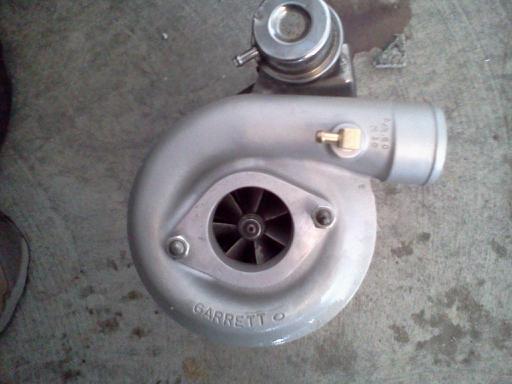
Couple minor updates. Hoping to do some real work on it this weekend. A while back I picked up a chunk of drive shaft out of a local machine shops scrap yard to use as part of the induction system for the turbo engine. A little mock up, there will be tapered runners to the head. Once sanded and primered it ought to look decent. I need the engine in the car to do a proper mock up for length though.    Also today I worked on making the cam sensor for the sequential EFI and coil on plug ignition by modifying the distributor some more and adding a sensor to the flat cap I made. It's actually just a prototype for now, I'll make a new plexiglass cover for the final product. First I cut the advance plate into a tab.  Then I took the top plexiglass plate and drilled a hole in it that the sensor fits through. I contemplated going with a full grommet set up, but the sensor really needs to sit on the plexiglass to get low enough for it to pick up the tab. I used a cut down transmission dipstick tube grommet to minimize vibration. I might zip tie or black RTV it on there. Then I drilled and tapped a hole for a 1/4-20 bolt.   Then plopped it on the engine. The wiring harness is pointing towards the coolant temp sensor so the wiring harness should look relatively clean there. If the sensor doesn't reliably pick up the tab I'll either bend the tab a bit or weld a washer or strip of metal to the top of it. Hopefully this is sufficient to run as a cam sensor.  
|
|
|
|
|
Joined: Jul 2004
Posts: 239
Contributor
|
|
Contributor
Joined: Jul 2004
Posts: 239 |
Silver Buick:
Thanks for the great thread. I've been following since you started and enjoying / learning a bunch.
Thanks:
Paul
|
|
|
|
|
Joined: Dec 2010
Posts: 535
Major Contributor
|
|
OP
Major Contributor
Joined: Dec 2010
Posts: 535 |
No problem. I did some more work in the last couple days. Made a final cam sensor cap and cleaned up the distributor shaft some. It won't win any art awards but it should work.  Also installed the flex plate so when I go to start the engine on the stand.  Made the center injector rail, connected it to the outer two with steel braided hose. Started on the wiring. I have all the signal wires for the ignition coils ran as well as the fuel injector wires. I need to run the power and ground wires for the coils still, but have to pick up some wire to finish it. I also ran the coolant temp sensor wires. I wanted to do the cam sensor wiring, but realized I don't know which wires do what =P So I have to sort that out. It's a stock hall effect cam sensor off a GM 4-cylinder if anyone happens to know. Drilled out the middle injector rail. Not very sophisticated but it works (well I hope it does...)  The injectors just peaking into the line. Actually they are pulled down a bit once installed as I found the connectors wouldn't plug in until I lifted the rail some.  This is where I ended the day. The injectors are in, the rails are linked up and the wiring harness is getting fatter. Lots of the wires might look the same, but actually they have different color stripes on them as well as text labeling printed on them.  And on the ignition side of the engine. 
|
|
|
|
|
Joined: Dec 2010
Posts: 535
Major Contributor
|
|
OP
Major Contributor
Joined: Dec 2010
Posts: 535 |
Started up working on this again. I didn't take any pictures of it, but I installed an OHC starter nose cone on a Buick 455 starter for a bit more oomph starting up. Got the project work board out for this one. I've added a few things to the list since I took the picture, like add oil and prime the system.  Got the exhaust system for the run stand sorted out. I may have to cut the pipe just before the bend and adjust from there once in the car, this will do for now.  . No where in Ely sells exhaust reducers so I had to improvise. So a few slices, some hammer taps and some welding fill. Due to my (lack) of awesome skills I had to fill a lot of gaps where the second pipe slide into that hole.  I also fabricated up the crankshaft sensor mount as well as did final mounting of the alternator, complete with new belt.  Got the sensor wiring routed safely around the exhaust. I'll put the alternator charging wire into the black loom when I wire it up.  Tomorrow's plan is to work on the fuel system and finish up the wiring.
|
|
|
|
|
Joined: Dec 2010
Posts: 535
Major Contributor
|
|
OP
Major Contributor
Joined: Dec 2010
Posts: 535 |
|
|
|
|
|
Joined: Dec 2010
Posts: 535
Major Contributor
|
|
OP
Major Contributor
Joined: Dec 2010
Posts: 535 |
Finished up the main wiring on it today. I still have to make my two connector plugs at the rear of the engine though. I installed the O2 sensor that I had forgotten to do and had to switch to the Holley throttle body due to me being an idiot. The way the Q-jet is oriented on the intake the throttle isn't pulled, it's pushed and for some reason that didn't click with me until today when I was looking to set up the return spring and start on the throttle bracket with a 200-4r cable. So with the Holley I flipped the direction or the primaries and secondaries to put the linkage on the other side and in a pull situation. I knocked out the venturi's and made some plates to seal up where the float bowls used to be also. Here is how it sits right now. I'll tie up the red power wire with the crank sensor wire before it's all done. I debated what color to paint the block off plates, but ultimately Pontiac Blue won. Red, black and silver were the other options. I forgot to take a picture of the other side of the engine, I have the wires pretty much loomed up.  Like the Q-jet, this thing was pretty grimy, so it only cleaned up so much, but looks a ton better than before. I have linkage brackets on order and should be in next week.  Some one was asking how I mounted my air temp sensor. I took the sensor to the hardware store, found a grommet that it fit tightly in, used a stepped drill bit to drill a hole in the base plate for the grommet and done. 
|
|
|
|
|
Joined: Apr 2007
Posts: 11
Active BB Member
|
|
Active BB Member
Joined: Apr 2007
Posts: 11 |
Interested in the project but probably too much of it is over my head. We have hypothesized and gathered parts from a Jeep 4.0 EFI, including harness & computer, to fit to a 250, and perhaps then to the SOHC 6. Not far along. Clifford intake machined for injectors. Modified dist with Jeep cam sensor that should work. I am a distant "neighbor" in Gardnerville, NV. Enjoying your posts! I have a 1938 Pontiac 4 dr, with a 1968 Firebird "Sprint" OHC 6, with 200 R4 fitted.
'49 Chev Styleline
'38 Pontiac, SOHC 6 "Sprint"
|
|
|
|
|
Joined: Dec 2010
Posts: 535
Major Contributor
|
|
OP
Major Contributor
Joined: Dec 2010
Posts: 535 |
The Jeep ports don't line up even close to the OHC head. I had a 4.0L EFI Jeep and actually have a spare intake manifold for it. It would take some serious cast aluminum cutting and welding to get things to work. I've only heard of a small handful of folks that have successfully used OE computers and wiring on a different car and never heard of someone successfully using an OE computer and harness on a different engine than what the OE computer was designed for (not counting stuff like a 305 chevy to a chevy 350, etc).
Fun fun. I finished the wiring a few nights ago. I'm planning on assembling the valvetrain this weekend and prime the oiling system to see how my modifications faired.
|
|
|
|
|
Joined: Nov 2004
Posts: 1,805 Likes: 1
1000 Post Club
|
|
1000 Post Club
Joined: Nov 2004
Posts: 1,805 Likes: 1 |
You might want to have another look at how you are holding the fuel rails onto the injectors.... The effective push off force is >150 # ..
do a calc on the opening in the rail area size #^2 x rail pressure....
Last edited by efi-diy; 10/20/13 01:28 PM.
51 GMC 4.2 turbo
Can't solved today's problems using the same technology/thinking that created them
|
|
|
|
|
Joined: Sep 2008
Posts: 3,669 Likes: 42
1000 Post Club
|
|
1000 Post Club
Joined: Sep 2008
Posts: 3,669 Likes: 42 |
Good point, that's why they are bolted directly to the intake in most apps.
Class III CNC Machinist/Programmer
|
|
|
|
|
Joined: Dec 2010
Posts: 535
Major Contributor
|
|
OP
Major Contributor
Joined: Dec 2010
Posts: 535 |
Half the things on this engine are an experiment, including the rail hold downs. A big part of why the whole thing is going to be tested on an engine run stand prior to being installed in the car. I just did oil pressure tests this weekend and have some work to do on the external oil line and regulator as it is having trouble giving me the pressure drop I want. With the injector rails, on the engine stand I'll easily be able to pressurize the fuel system without the engine running. With the pump I have I can take the static pressure up to 90psi or so. I might spill some fuel if it comes loose, but it'll just be lost fuel and I won't start the test if there is a point of ignition around. Honestly I want to know if the rails will leak around the O-rings as I single pass drilled them with no special finish. That's the real wild card. The hold downs I can run a bead of weld or gusset a small line of steel to prevent bending upwards if needed. Worse case I'll safety wire the injectors to the rail and do away with the hold downs all together. It's going into a '69 Firebird (I know the exhaust will have to be reworked to fit the chassis). Picked this car up in Alabama and drove it home. It had a non-original 400/TH400 combination in it. I've yanked the engine and trans out a while ago and have installed the L6 frame mounts in it. I am going to rebuild a TH2004r I have for it and put in a set of 4.56 gears that just recently showed up as well.   Here is the throttle bracket with TV cable attachment installed. I will probably weld on a tube or pulley wheel to support the near 90* bend(s) in the cable towards the firewall. As it sat there, I stood behind the engine and had no issues actuating the throttle and it returning. I'll probably have to get the Holley linkage kit for the 700r4/2004r TV cable.  Here is what I've accomplished in the last week: Got the plugs completed.  I was looking in the service manual and saw the tool they used to remove the valve springs and have made something similar that I think will work out of a Buick rocker arm and old allen wrench.   Getting closer to a running engine. I assembled the valvetrain, set the cam timing, topped off the oil and started priming the system. Here is the used C-cam. Its the 175HP 1bbl cam. Figured I'd use this cam to get the engine running and driving and after I have the car on the road for a while I'll swap to a bigger E-cam, 215HP 4bbl cam. Notice the cam lubricates the followers directly.  Here are the lash adjusters in place before I set the cam housing on. I greased up the cam and followers before assembly.  The stock oil pressure is set at around 30psi, so I swapped the stock relief spring with a spare Buick white spring I had, which is supposed to be 60psi in the Buick (my experience says 75psi). I primed the system up and the system pressurized to 95psi, so I cut three coils off and it dropped to 70psi, which I am good with.   But then I ran into a problem. My external oil pressure regulator isn't dropping the pressure to where I need it to be. The spring on the left is the spring that came in the regulator, so I went to the hardware store and bought the spring on the right, trimmed it down twice and still can not bleed off even close to enough pressure. So I figure I'll have to go to a regulator that has a return line. I have one more trick up my sleeve to try and get this regulator to work for me. I'm going to install a valve in the external line and see if I can drop the volume to the regulator and see if I can gain the pressure control I need there. Basically an external adjustable orfice tube, lol.  I have the wiring harness off for the cam housing installation. Took about 5 minutes to pull it off the engine. I'll tidy it up for re-installation. I'm pleased though with how easy it was to remove.  Now for my valvespring compressor  I took a spare 9mm allen wrench and a universal stamped steel Buick rocker arm and began cutting, grinding and welding and came up with this. The T shaped one has a notch at the end to hook the oil galley in the lash adjuster hole and I welded a nub on the end of the rocker arm to keep the T part from sliding out. I stuck a standard 6 point impact socket and extensions on the end of the allen handle for extra leverage. I'm considering cutting down the allen handle and simply using the socket and extension for the lever. More compact.  In action. I originally left the loop on the rocker in place, though shaved a bit, for structural reasons, but I think I can safely remove it if I box in the rocker below the allen shaft and on the other side between the opening and slot for the T.  So where I sit is correcting the external pressure regulator control and tidying up my wiring harness for re-install. Then I'll set it up on the engine run stand and run through the fuel and spark checks before actually firing up the engine.
|
|
|
|
|
Joined: Oct 2007
Posts: 5,015 Likes: 47
1000 Post Club
|
|
1000 Post Club
Joined: Oct 2007
Posts: 5,015 Likes: 47 |
I was not following this build until this morning. The tool drew me in. The places I have lived before are littered with home made parts and tools that didn't work. When found by archeologists in the future the will think"WTF?" I have a theroy that most tools found from ancient cultures are the ones they threw away. They kept the good ones. Yours looks like a keeper.  I went back and read it all. I'm into it now. 
"I wonder if God created man because he was disappointed in the monkey?" Mark Twain
|
|
|
|
|
Joined: May 2009
Posts: 493
Contributor
|
|
Contributor
Joined: May 2009
Posts: 493 |
Nice work SilverBuick. I like your ambition.
This has nothing to do with your technical content and is only an opinion: The red on the cam cover looks good but not so much elsewhere.
|
|
|
|
|
Joined: Dec 2010
Posts: 535
Major Contributor
|
|
OP
Major Contributor
Joined: Dec 2010
Posts: 535 |
|
|
|
|
|
Joined: Oct 2006
Posts: 185
Contributor
|
|
Contributor
Joined: Oct 2006
Posts: 185 |
Randal, don't you hook your fuel rails down. It looks like they are just sitting there not secured. Am I missing something? I am having a machinist make me an aluminum piece to fit on top of the 4-71 blower that will hold 4 EFI injectors.
|
|
|
|
|
Joined: Dec 2010
Posts: 18
Active BB Member
|
|
Active BB Member
Joined: Dec 2010
Posts: 18 |
So if I understand this you're using MAP not MAF, right" I was trying to figure our why you didn't just turn the Holley 90 degrees to get 'pull inline'. I suppose a later model throttle body would look wrong....
|
|
|
|
|
Joined: Dec 2010
Posts: 535
Major Contributor
|
|
OP
Major Contributor
Joined: Dec 2010
Posts: 535 |
Gary, I think you are just looking at the pictures I have the cam housing and hooks removed. This intake is a temporary intake so the solutions just need to be functional. Here is a picture with the hooks in place. I may need to gusset them if I think the are pushing too hard when I go to pressure up the fuel system on the engine stand (engine off).  It is a MAP speed density system, no MAF at all. I have a 90* Ford intake fitting and a large single blade throttle body and I could not get the 90* to fit in a way I was happy with. The giant pictures that are screwing up the width of this thread are a mock up of what I'll be doing for a final intake manifold. Basically an inline tube with a single throttle body on the front and then six equal length runners from the main tube.
|
|
|
|
|
Joined: Dec 2010
Posts: 535
Major Contributor
|
|
OP
Major Contributor
Joined: Dec 2010
Posts: 535 |
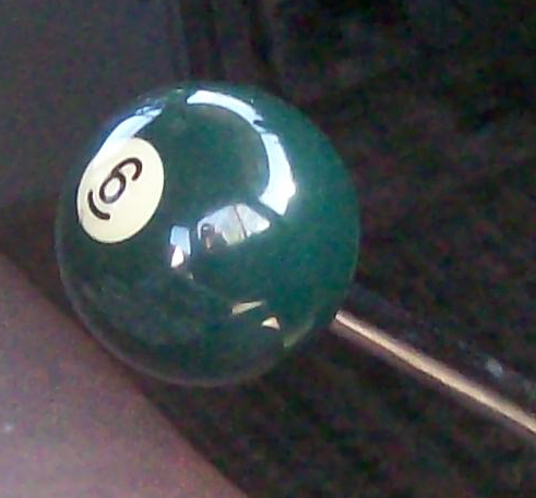
Some updates. Since I want to get the car driving as soon as possible I have attempted a rebuild on the 200-4r I had collecting dust in the corner. Of course I won't know if I was successful until it's installed in the car. It used to live behind the 231 V6 in my Skylark for several years.  Fortunately it was nice and clean inside. Probably could of gotten away with just the shift kit as I found that the friction plates looked good and every spring I replaced in the valvebody was the same color as the one in the "shift improver kit", which is different than a shift kit.  Everything went back in... Hope it works! I am actively looking for the cheapest torque converter I can find that is at least a 2,000rpm stall and locks up.  This upcoming weekend I hope to install some 4.56 gears in the Firebird and I've bought the 4-speed version of this shifter (like in the video below), which of course there are cheaper shifters that accomplish the same thing, but the novelty will be a riot with the 4.56 gears I think. sE9swmcMt7BR+zZZtsNw~~60_35.JPG) http://www.youtube.com/watch?feature=player_embedded&v=1dyIZlL_HU0 http://www.youtube.com/watch?feature=player_embedded&v=1dyIZlL_HU0Going back the inline six. Got the external oil line and regulator working. I had to down size the feed line because it was bleeding off the main line pressure as well. Right now I have a temporary 1/8th inch fuel line (rated to like 120psi..) for the external line, but I'll order up something more permanent. Worse case I'll go with some copper line since there isn't any flexing once installed. I need to come up with an oil return location. there is a rubber plug on the side of the oil fill tube so I might install the return into that or make a new oil fill cap with the return line fitting on it. An interesting observation on the main line oil pressure gauge. I noticed this gauge takes a while to show pressure build up compared to the electric oil pressure gauge on my Skylark when I did a back to back test. On this engine both oil pressure gauges come off the same tee and one is clearly slower in responding, the one with the long plastic line. I think the air in the line causes the long delay and slow response in oil pressure, which is a common thing in mechanical oil pressure gauges. http://www.youtube.com/watch?v=DcDLioxtjvE&feature=youtu.beI've got the wiring cleaned up and installed back on the engine. As it sits now it's ready to fire up if it passes the fuel system pressure test. I need to finish building the engine run stand control panel, get some hoses for the radiator connection then I should be able to fire it up!
|
|
|
|
|
Joined: Dec 2010
Posts: 535
Major Contributor
|
|
OP
Major Contributor
Joined: Dec 2010
Posts: 535 |
I've been looking at some EGT sensors and input boards for the Megasquirt as well. I am considering drilling the exhaust manifold for the EGT sensors and retaining the exhaust manifold for the turbo.
I am hoping for enough resolution on the EGT's to be able to do some individual cylinder fuel trims to balance out the fuel in each cylinder and just have a single O2 sensor to know I'm still in the general AFR ballpark. When turbo'd it would allow me to set up some safety systems if a cylinder gets hot (lean out) or goes cold.
What's the furthest from the head some of you have mounted a turbo? I'm thinking I will route the single 2.5" exhaust over to the passenger side of the car via the space just past the torque converter and back up into the passenger side of the engine bay. It'll be quite a run of tubing. I'll see if I can come up with a better solution once this engine is in the car and can see what room I have to work with.
|
|
|
|
|
Joined: Dec 2010
Posts: 535
Major Contributor
|
|
OP
Major Contributor
Joined: Dec 2010
Posts: 535 |
Gambled and lost. Definitely have a 2.73 gear set (2-series) and not 3.08 (3-series), damn. So for $180 I have an appropriate carrier and mini-spool on its way. I'll have $280 into the rear axle when done. Got the shop and tools cleaned up and organized today. Got the engine back on the run stand and found some radiator hoses from NAPA. Hopefully the radiator doesn't leak =P I have two mufflers ready for testing as well. Ordered a pile of things today on top of the carrier and mini-spool. I have a 2000-2500 stall torque converter, TV cable, Holley carb TV cable kit, and a dipstick tube and stick on the way. Getting ready for install, hopefully no serious hiccups when I do the fuel pressure test and start up.   Due to a friend's huge generosity I may be going to a reverse flow cooling system sooner rather than later! He said he has an automotive remote electric water pump and controller that is about ten years old but had never been installed/used that he is just going to give me! So I went down to NAPA and asked them what the largest diameter heater hose they keep in stock was and I was delighted to hear they had 50ft of 1" heater hose. So I went to the hardware store and picked up a pair of 1" steel water nipples and welded them to a pair of steel freeze plugs. Due to heat while welding, changing the inside shape, etc I may have to find a way to positively retain them in the block. Like a set screw or plate. I'll cross that bridge later. Here is a pair of mock up photos.   Oh yeah, started on a control panel as well. Just have to wire it up. 
|
|
|
|
0 members (),
152
guests, and
55
robots. |
|
Key:
Admin,
Global Mod,
Mod
|
|
|
|