The DIYautotune wires come nicely labeled with pin number and function (as well as being color coded).
Basically switched (fused) power to pin 28, ground most the grounds straight to the battery (1,2,8-11).
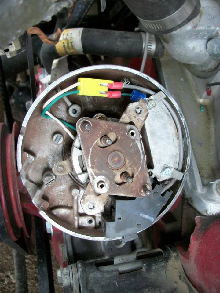
Tach In wire, Pin 24, will go to your HEI pickup coil like in my photo below. I grounded the signal locally in the distributor, which is also how the diagram shows it. If that causes issues then change the ground to one of the wires going to the battery (just move the wire).
To control spark, you will still need +12v connected to the "+" of the HEI cap. Probably link this to the fuel pump relay(or relay controlled by the Fuel Pump output, Pin 37, so it only has +12v while the engine shows rpm. It will save you from burning up your coil down the road from having the key on, engine off. The ground side will need to be connected to Pin 36, this is the wire the controls the timing. Again, these wires are labeled right on the wire as such in the harness (Pin#, and Function).
You will need to lock the HEI's mechanical advance in place. Easiest way to do this is either ziptie or wire tie the advance mechanism by the posts that have springs so they cannot move. Then simply leave the vacuum advance disconnected.
Then set the megasquirt settings to the number of cylinders, and set your coil dwell (I'd have to look it up for HEI single coils, probably ~3.0ms). Then open the timing table and set the whole table to like 15º to start. Your engine should start at this point. From here it's tuning. Set your rpm and manifold pressure bins to what you think the engine will run to. Aka, you don't need the rpm side to go to 8,000 rpm unless you plan on running it that high. 500 to 6500 is probably appropriate. Kpa wise, you need to see how much vacuum the engine is pulling, but likely 25kPa to 200kPa (~15psi boost). You can tighten up these numbers as part of the tuning process later. You'll realize it's really easy after you make a few changes.
Coolant and Temp sensors are wired in the same way, one side goes to the appropriate Pin (20,21), the harness is labeled for each sensor, and the other wire for those sensors go to a common "sensor" ground, which is Pin #19. Only ground sensors to Pin 19.
O2 sensors are easy, if using say a common LC-1 or LC-2, it has two outputs, one output wire goes to Pin 23. The other can be used on an external gauge or left disconnected. I've not used any other brand O2 sensor, but all should have an ECU out wire.
This is a very generic wiring diagram. The DIYautotune harness uses most these colors, but you can go by the pin number as well.
This is how I ran the HEI in my Skylark from 2009 to 2011 (then I went to a crank trigger and ran this way as a cam sensor). It's the 7-pin small plug pickup coil, but the 4-pin pickup coil works the same, just a bigger plug. The grey wire (from DIYautotune) goes to Pin 24, and the other side I simply grounded there. It's generally not very picky which wire connects to which since it's reading a wave, but if you seem to have trigger issues, simply swap the two wires and start it back up and see if the issues go away. I drilled and roll pinned my mechanical advance, I don't recommend that, simply tie those posts together some how.