|
|
Joined: Sep 2003
Posts: 237
Contributor
|
OP

Contributor
Joined: Sep 2003
Posts: 237 |
A few pics of the intake manifold. The idea has been in slow development for about...oh wow....like 3 years. I've gone through a number of different variations and materials. And it has led up to this piece. I brought it to Waterdown so a few members have seen this already. Now bear in mind, this is meant to be part of a system; the idea is that this engine will ultimately have a turbocharger. The first bank of injectors (shown installed, but not supported by brackets) runs 87 octane. The more inclined bank will run from a seperate fuel system with its own pump, filter, regulator, lines et. It will run some type of race fuel, perhaps 109 octane to begin with. So there's a lot of complexity in the fuel system. But it will enable me to drive on the street at reasonable cost while still having access to the high octane the turbo would require. I'm hoping that with the turbo, the complete system will make 300 hp on a stock head & engine. At my pace though, it'll be a while before I get to test this theory. Questions and critique always welcome     
|
|
|
|
|
Joined: Sep 2005
Posts: 101
Contributor
|
|
Contributor
Joined: Sep 2005
Posts: 101 |
Wheel 2 Wheel Powertrain has done an "octane on demand" system in this car. Sounds like you're on the right track. Nice work. http://w2wpowertrain.com/t-novabuild-2.aspx
|
|
|
|
|
Joined: Jul 2000
Posts: 4,585 Likes: 19
1000 Post Club
|
|
1000 Post Club
Joined: Jul 2000
Posts: 4,585 Likes: 19 |
That looks very Nice. I have to ask where did you get the D shaped tubing? For the plenuim? and the Belled tubing. Very Sweet.
Larry/Twisted6 [oooooo] Adding CFM adds boost  God doesn't like ugly.
|
|
|
|
|
Joined: Sep 2003
Posts: 237
Contributor
|
|
OP
Contributor
Joined: Sep 2003
Posts: 237 |
Thanks twisted! The D extrusion as well as the runner tubing and the velocity stacks are from http://www.rossmachineracing.com/ Custom manifolds are essentially what they do so it was a pretty big leg up on fabricating. Oh, I bought the fuel rail extrusion and end caps from them as well. Zeke - that is an awesome link! I have never actually seen anyone do a double fuel system like my own - although I have to admit it's been a few years since I seriously looked. Pretty cool build.
|
|
|
|
|
Joined: Jul 2000
Posts: 4,585 Likes: 19
1000 Post Club
|
|
1000 Post Club
Joined: Jul 2000
Posts: 4,585 Likes: 19 |
Thanks Greg That D shaped tubing may come in handy hehe
Larry/Twisted6 [oooooo] Adding CFM adds boost God doesn't like ugly.
|
|
|
|
|
Joined: Mar 2004
Posts: 565
Major Contributor
|
|
Major Contributor
Joined: Mar 2004
Posts: 565 |
Greg,
I like your design! Very nice welding too. The "roll of dimes" is superb! I can see a lot of thought went into this design and commend you on your fabrication and design. I love to see real hotrodders in action. I too did a custom intake a while ago and it's still not on the car. Don't feel bad about the time frame. Good design takes time.
RapRap
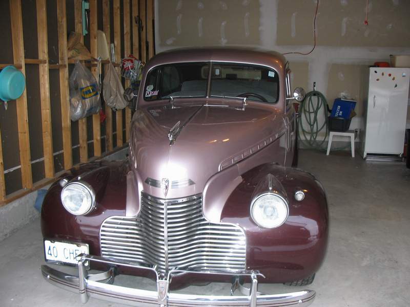
1940 ChoppedChevyCoupe
Loud Pipes Saves Lives!
|
|
|
|
|
Joined: Dec 2000
Posts: 3,332
1000 Post Club
|
|
1000 Post Club
Joined: Dec 2000
Posts: 3,332 |
G; Yes; VERY IMPRESSIVE!! :rolleyes: I'm sure it will work as well as it looks.  Happy trails.
John M., I.I. #3370
"There are no shortcuts to any place worth going". -Anon
|
|
|
|
|
Joined: Apr 2004
Posts: 3,556 Likes: 35
1000 Post Club
|
|
1000 Post Club
Joined: Apr 2004
Posts: 3,556 Likes: 35 |
you should go into production making those. very nice. what size is the diameter of the port runners? tom
Inliner Member 1716 65 Chevelle Wagon and 41 Hudson Pickup Information and parts www.12bolt.com
|
|
|
|
|
Joined: Feb 2001
Posts: 208
Contributor
|
|
Contributor
Joined: Feb 2001
Posts: 208 |
That looks beautiful and I'm really curious what your final outcome will be and how good it works. Keep us informed!
1968 Camaro - 250 (No, I'm not gonna drop a 350 in it!....Jeez!)
1968 C-10 with 2 extra cylinders
|
|
|
|
|
Joined: May 2000
Posts: 1,464
1000 Post Club
|
|
1000 Post Club
Joined: May 2000
Posts: 1,464 |
Superb craftsmanship and ingenuity! Keep us informed.
FORD 300 inline six - THE BEST KEPT SECRET IN DRAG RACING!
|
|
|
|
|
Joined: Sep 2003
Posts: 237
Contributor
|
|
OP
Contributor
Joined: Sep 2003
Posts: 237 |
I have to be sure the credit is going to the right place on a few of the comments: I've done everything on this intake with the ONE exception of the welding, which I had to get done. I just didn't have the amps available to pull off such a job on aluminum and frankly it wouldn't have been done as well as that. tlowe - runners are 1.5 inch. They're large compared to stock but not really excessive in light of what I may want from this engine in the future. Design notes: That d-extrusion is way too big, about twice the plenum volume necessary for the engine. This usually has the effect of a small gain in high end at the trade off of response and sometimes low end. Given this isn't a tuned intake and neither was the stock the low end loss won't happen (never there) but the response will be a serious problem. On the other hand I've got too much throttle for this size engine which will partly cancel out the effect of the plenum. Basically I've left these open to be tuned: because the end caps are removable I can add dead volume in there to take up space and increase response. I can also modulate the throttles through different linkage geometries and opening rates (progressive throttles for example). So there's a fair bit of tuning to still happen here but you can see where I'm going. By the way, just turned 22 a little while ago so if I sometimes seem a bit green its not for lack of effort I appreciate all the support here guys, keeps me going sometimes.
|
|
|
|
|
Joined: Jul 2000
Posts: 4,585 Likes: 19
1000 Post Club
|
|
1000 Post Club
Joined: Jul 2000
Posts: 4,585 Likes: 19 |
well happy Late BD. mine was on the first.
But yu have done a great job on it so far.
Larry/Twisted6 [oooooo] Adding CFM adds boost God doesn't like ugly.
|
|
|
|
|
Joined: Sep 2005
Posts: 101
Contributor
|
|
Contributor
Joined: Sep 2005
Posts: 101 |
What are you going to put this on, engine I mean?
What vehicle will the setup be installed in?
|
|
|
|
|
Joined: Sep 2003
Posts: 237
Contributor
|
|
OP
Contributor
Joined: Sep 2003
Posts: 237 |
Well right now its a 230 Chevy in an 81 Trans Am. I do hope to put together a 250 later though with a light casting 250 crank and rotating assembly.
|
|
|
|
|
Joined: Sep 2000
Posts: 588
Major Contributor
|
|
Major Contributor
Joined: Sep 2000
Posts: 588 |
I was one of the members at Waterdown who saw it and got to touch it. Greg has had it out to our brunches over the winter/spring time as well and his progress has been very good. It is a very impressive looking piece. Kinda funny at Waterdown as one of the guys looking at it is running an early Chevy coupe with a full house GMC and 3 carbs. I can't imagine the time frame difference between the old (302 with 3 carbs) and the new (250 with turbo/F.I.) but it is really good to see the participation of the younger crowd. Makes you wonder where the next step will take us.
Ontario Inliners
1965 Chevelle
1940 Chev
1965 Chev Pick-up
1970 MGB Roadster
|
|
|
|
|
Joined: Aug 2007
Posts: 39
Active BB Member
|
|
Active BB Member
Joined: Aug 2007
Posts: 39 |
Greg,
Very nice work.
I had an late uncle who was a welder in Kitchener (Daniells Welding) Must be something in the ar there. That is just beautiful. I made my own intake from steel . 6 tillotson snowmobile carbs on a slant 6 but after seeing yours i am hiding mine. My hat is off to you. Superb craftsmanship
D
|
|
|
|
|
Joined: Sep 2004
Posts: 5,839 Likes: 1
1000 Post Club
|
|
1000 Post Club
Joined: Sep 2004
Posts: 5,839 Likes: 1 |
Greg,
Looks nice,
Do you have any pics of the intake runner?
Just curious on how that looks inside the intake runner/port.
MBHD
12 port SDS EFI 
|
|
|
|
|
Joined: Apr 2004
Posts: 3,556 Likes: 35
1000 Post Club
|
|
1000 Post Club
Joined: Apr 2004
Posts: 3,556 Likes: 35 |
greg, i thought of a really good way to critic your manifold. i could try it on my engine. 
Inliner Member 1716 65 Chevelle Wagon and 41 Hudson Pickup Information and parts www.12bolt.com
|
|
|
|
|
Joined: Sep 2003
Posts: 237
Contributor
|
|
OP
Contributor
Joined: Sep 2003
Posts: 237 |
MBHD - I'll have to find some pics of the inside of the runners. I think I've kept the profile pretty smooth the whole way but I'll let you judge by the pictures. I'm in the middle of moving so I'll find those pics and upload them later this week.
tlowe - if we were closer i would go for it; once I have the second fuel circuit going this thing will just beg for a few psi of boost.
So I've been busy guys but I managed to get about 12 hours in yesterday in the garage. Got a fair bit done on the intake, slow going in some places. Overall decent progress. I had the surge tank assembled yesterday on the work bench and plumbed into the fuel rail on the full assembled intake. I gave it about at hour at 50 psi, everything looks tight and well sealed. Wiring harness is about 50% done with all sensors checking out so far. I have not yet triggered the injectors.
I'm going to try to make a run for it and finish this this up for next sunday for a meet up here. So HOPEFULLY I will be able to post more pictures for you guys in a few days, figure on friday. Wish me luck
|
|
|
|
|
Joined: Feb 2007
Posts: 13
Active BB Member
|
|
Active BB Member
Joined: Feb 2007
Posts: 13 |
hey Greg,
price to buy one ?
we can buy one?
minus thorttle bodys and his bases, all plenum
list the price plz
regards
TRY 4 DIGITS BARRIER HP
This is possible with help
|
|
|
|
|
Joined: Jun 2005
Posts: 148
Contributor
|
|
Contributor
Joined: Jun 2005
Posts: 148 |
Greg! Amazing job!!!!  Can you tell me how you calculate your plenum volume?? I´m researching to make my Turbo intake Manifold, and it´s really hard to find some good information about intake manifold volume, intake runners diamenter and lenght!! Really good looking on the D extrusion and velocity stacks... Hope to hear from your progress soon..
|
|
|
|
|
Joined: Sep 2004
Posts: 5,839 Likes: 1
1000 Post Club
|
|
1000 Post Club
Joined: Sep 2004
Posts: 5,839 Likes: 1 |
Douglas, Intake runner length does not make much difference in power,but if you want the most top end power,make them short. http://www.rossmachineracing.com/ http://www.ka-t.org/intakemanifoldbasic.php I believe they will help you figure your intake volume needed. I bought 2" aluminum tubing w/a .120 wall thickness that worked for my cylinder head,what size are your intake ports? That is for my runners. IIRC,my ports are 1.71" The 2" tubing w/a .120 wall comes out to be 1.76",so it is a little bigger than my cyl head intake port so I will match port the intake port to 1.76" ,the same as the 2" id of the tubing. Did you get the pro port job? If so,,I think they are 1.80"??? Email me if you want more info. MBHD
12 port SDS EFI
|
|
|
|
|
Joined: Jun 2005
Posts: 148
Contributor
|
|
Contributor
Joined: Jun 2005
Posts: 148 |
Hank! My cylinder head is a Pro Porting one. 1.8" intake ports! What tubing size can I use in my cylinder head?? That D Shaped tubing from ROSS Machine Racing will work for my car?? I have no idea of how to build my intake Manifold!!!  Here is some pics of how I´m building my set up, with turbocharger on the correct position.... (maybe with some pics of the set up someone can help me better.... ) 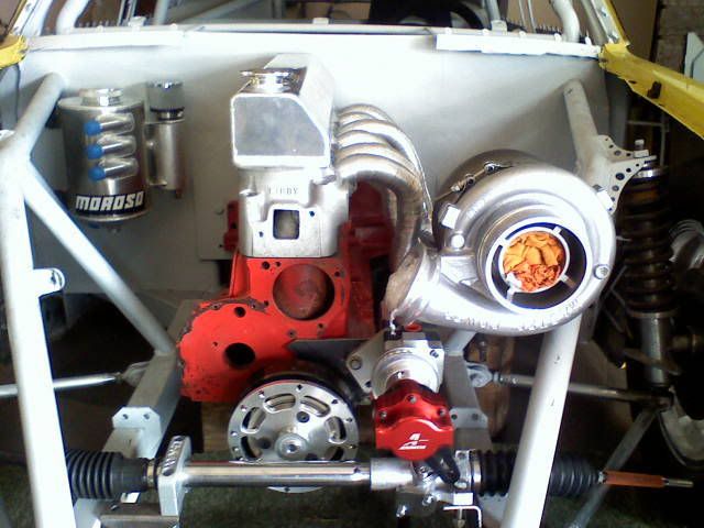 "Fake" exhaust manifold with aluminum tubing coming from intake ports (Just to have an idea of how it will looks like...) 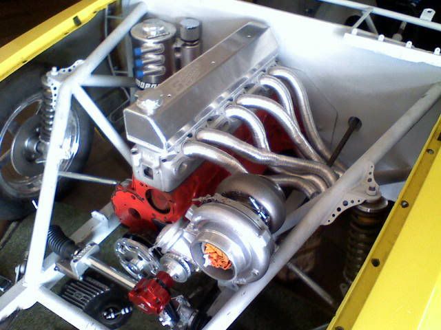 And Air/Water Intercooler inside of the car, on the passenger side... Lots of 4" tubing going in and out of the car!!! 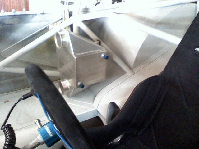
|
|
|
|
|
Joined: Sep 2003
Posts: 237
Contributor
|
|
OP
Contributor
Joined: Sep 2003
Posts: 237 |
Sorry guys, none for sale and no plans to make them available. There's a lot of machining to fabricate it the way that I did it but it worked because I had my college machine shop there and some help from a generous co-op employer. I thought on it for a while and I can't see making many of these the way I did; you'd have to do some more thinking on the design. And of course most of the design was done as it was to accommodate the two banks of injectors and I imagine the crowd interested in those would be even smaller than the crowd interested in injection.... ***Bare in mind I haven't run this thing yet so while I've researched this stuff I seen it myself (yet)*** Plenum volume: I chose mine on ease of fabricating since this is my first project and I'm doing this all on my own.....can't expect the world yet. I've seen it one or two places but www.grapeaperacing.com has it summarized decently: "There is not going to be a simple answer to the needed plenum volume for a given application or rpm range. The good thing about plenum volume is that there is a pretty wide range that it can be and still be effective, so general rules work well. The following guidelines are for engine operating in the 5000-6000 rpm rage. V8's with one large plenum feeding all 8 cylinders does not work all that well as far as the Helmholtz resonator goes, but if this is the case, plenum volume should be about 40-50% of total cylinder displacement. On a four cylinder engine 50- 60% works well. For 3 cylinders (6 cylinder engine with two plenums), each plenum needs to be about 65-80% of the 3 cylinders it feeds. If a boost is desired in a higher rpm range, closer 7000-7500 rpm, the plenum will need to be 10-15% smaller. To get a boost in the 2500-3500 rpm range, it will need to need about 30% larger." I don't have the numbers in front of me but my plenum ends up being something like 200% of what it needs to be. For that reason I left the ends caps as sealed joints rather then having then welded; I intend to add ballast volume (gasoline resistant plastic maybe? not sure) as a tuning and experimenting means. In this particular case it is easier to remove volume than add it (as many do with throttle body spacers). I would recommend the Grape site. I waited forever for Jeff Hartman's Engine Management book (for the computer stuff) and who do they basically copy/paste for the intake section.....grape.... Douglas Carbonera - awesome looking setup man, just awesome. Someday I'm going to be into cars the way you are. Right now I'm broke, just done school and no job yet, so it is all about turning wrenches while savings money and doing all the work myself. Which is its own challenge but I won't feel too bad when I can actually afford a decent head and a turbo.... take care guys - I'll keep at it so I have some pictures for you soon
|
|
|
|
|
Joined: Sep 2004
Posts: 5,839 Likes: 1
1000 Post Club
|
|
1000 Post Club
Joined: Sep 2004
Posts: 5,839 Likes: 1 |
[QUOTE]Originally posted by Douglas Carbonera: [QB] Hank! My cylinder head is a Pro Porting one. 1.8" intake ports! What tubing size can I use in my cylinder head?? That D Shaped tubing from ROSS Machine Racing will work for my car?? I have no idea of how to build my intake Manifold!!! Douglas, I have the "D" shaped extrusion,it will work for you also. Not sure if you can find a 2 @ 1/16th" tubing w/a .120 wall aluminum? That would be roughly 1.82" ID & your port is 1.80,, or I am sure you can find 2.125" but that will have an ID of 1.88" If the tubing has a .120"wall,,,,multiply by two = .240 then subtract that from the tubing diameter,that will give you the inside diameter. Ross,does not make big enough velocity stacks for your application or mine,I asked. So I am just going to make my own. You can have those made,just download a pic from Ross machine & give the pic to your local machinist & have them copy it. Just look @ the velocity stacks from Ross,it has a .250" step (the velocity stack) there Plenums are .250" thick it is pretty basic how they are made,esp. for round port velocity stacks(you just make them on a lathe,CNC(computerized lathes)are the best. And from the looks of your main cap girdle,that machinist will have no problem making the velocity stacks. I really wanted some velocity stacks from Mighty 6 but his brother said he has no time to make them,,,,really pieces of art, if you look @ his website & look @ his intake ports/velocity stacks. MBHD
12 port SDS EFI
|
|
|
|
|
Joined: Jun 2007
Posts: 1,411
1000 Post Club
|
|
1000 Post Club
Joined: Jun 2007
Posts: 1,411 |
Mr. Douglas Carbonera, I was wondering how you get in touch with Pro Porting? That looks like the 'Sissel' Head, if it is similar, aren't those the intakes the flex tube is in? (not trying to nit pick here, just trying to learn)
My, what a steep learning curve. Erik II#5155
|
|
|
|
|
Joined: Jun 2005
Posts: 148
Contributor
|
|
Contributor
Joined: Jun 2005
Posts: 148 |
Thanks Greg!! So.. While you are not working, why don´t you make some intake manifolds for the Inliners here to get some money??? And please, send us more pics of your great work!! Hank! Thanks for the tips!!! I´ll see If I have here the 2"1/16 tubing with .120 wall!!! And about the velocity stacks, they have to be "FLAT" in relation of the bottom of the plenum (Like Greg´s intake Manifold), or they have to be up to the bottom of the plenum (Like Mighty6 one)??? I´m just a little confused.... Nexxussian: Yes! It´s a Sissell aluminum 12 port head, Pro Porting. And Yes, the flex tubing is on the intakes, just to keep the tubing in place to a preview design of the exhaust manifold...
|
|
|
|
|
Joined: Sep 2004
Posts: 5,839 Likes: 1
1000 Post Club
|
|
1000 Post Club
Joined: Sep 2004
Posts: 5,839 Likes: 1 |
Douglas, that is one way to make a manifold. Mighty 6's velocity stacks are long & tappered. So it is bigger @ the top of the runner & gets smaller as it gets closer to the intake port on the cyl head thus increasing velocity. Here is a better design,,,well sorta : http://www.sdsefi.com/techinta.htm It is supposed to be better if you make your velocity stacks protrude into the plenum area. But the pic shows a bad velocity stack,the top should be curved more for a more full radious. More like this http://www.gravesport.com/cgi-bin/shopper?preadd=action&key=AB__003 Mighty6 has the correct idea,that is why I wanted his brother to make me the same type of velocity stacks,picture perfect!! http://www.mighty6.com/pics-sept-05/DSC00005.jpg MBHD
12 port SDS EFI
|
|
|
|
|
Joined: Jun 2005
Posts: 148
Contributor
|
|
Contributor
Joined: Jun 2005
Posts: 148 |
Hank:
That intake tubing with velocity stacks used on the Mighty6 engine is a Billet piece, fully CNC machined??
There is any machine shop that sells it, or it have to be fabricated??
|
|
|
|
|
Joined: Sep 2004
Posts: 5,839 Likes: 1
1000 Post Club
|
|
1000 Post Club
Joined: Sep 2004
Posts: 5,839 Likes: 1 |
Douglas,
Those are billet pieces.
There are machine shops that will make them but they want too much money for my income.
I do not know if Mighty 6's brother has a CNC machine?
I believe they make the flanges,or can make the flanges on your Sissell head,because they have a CNC machine??? Not sure???
I believe they(the velocity stacks) are not CNC machined because it took him a while to make them,but if he had them CNC'd he should have a program to make more???
Maybe ask him in a PM?
I remember you saying Brazil has a strong machining industry?
A local machinist should be able to make you some?
Nobody sells them ,like they have them in stock.
Ask Mighty6 his dimentions of his velocity stacks,like the Bell mouth/entry is 2.250",, then is narrows down to 1.8"(on the other end) which is the size of your port,& the length is 6"s or there abouts???
I have mandrel bent tubing I can send you pics of what I am doing,if you like to see them?
I do not want my intake manifold sticking out of my hood,therefore I have 2" mandrel bent pieces for the intake runners.
Nothing is cut or put together ,but I have some of the pieces to make a manifold.
The ports are a 45 degree coming out of your cylinder head.
MBHD
12 port SDS EFI
|
|
|
|
|
Joined: Jun 2005
Posts: 148
Contributor
|
|
Contributor
Joined: Jun 2005
Posts: 148 |
Hank! Mike sent me the Intake and Exhaust flanges for the head! It´s OK about this! I´m worried about the intake tubing with velocity Stacks... On the Mighty6 inatek, the tubing/velocity stacks are just one piece, made billet?? If yes, it will be very expensive to do it for 6 ports...  I´ll try to contact Mighty6 to know more about his manifold!! And, YES, SEND ME THOSE PICTURES!!!! Thanks Hank!
|
|
|
|
|
Joined: Sep 2004
Posts: 5,839 Likes: 1
1000 Post Club
|
|
1000 Post Club
Joined: Sep 2004
Posts: 5,839 Likes: 1 |
Douglas,
yes, those flanges you got from Mike are good.
Mighty6's velocity stacks are individual pieces,6 total.
Yes, solid billet.
6 aluminum billet pieces would cost about,,,10-20 dollars each x 6. not too much?
Just the little short velocity stacks from Ross are like $40 each US dollars.
I will send the pics.
Have not seen any package from your friend in Florida???
MBHD
12 port SDS EFI
|
|
|
|
|
Joined: Sep 2003
Posts: 237
Contributor
|
|
OP
Contributor
Joined: Sep 2003
Posts: 237 |
And here I am now with the promised pictures, perhaps with the exception of the one of the inside profile of the runner. I haven't had my computer fired up yet this week (as I'm moving, on the girlfriends computer right now) so I'm still going after that. In roughly chronological order here is how I spent my wrenching hours this week:  The other team members resting up.  Intake, spare head, firebird ('81, trans am actually), computer setup for later tuning  Doing some early computer testing. There was a lot to do so every time i go slowed down somewhere I just switched over to working on something else for a bit. Here I'm running the engine with the MAP (manifold absolute pressure) sensor hooked to the intake, just to get an idea what sort of running pressures I should expect. I've never had a vacuum gauge on an engine before.  My surge tank. There are 4 lines running to it: low pressure feed (from stock mechanical pump, max 7psi), low pressure return (to tank), high pressure feed (EFI pump, ~50 psi @ WOT as it is vacuum referenced) and high pressure return from the regulator.  I'm not really a fan of brass fittings like these, there is a few places where you know they'll create restriction but they're all that is in the budget at the moment.  THIS is where I went wrong. The sealing is accomplished by the main o-ring in the middle. The four perimeter fasteners are through bolts with nuts on the underside with washers. They protrude into the tank, but I hoped with enough thread sealant or perhaps epoxy they'd seal and it would be sufficient for the low pressure in question. Not so. The access ended up being very difficult to correctly apply epoxy and the pressure was enough in the tank even with the return that I kept getting consistent small fuel leaks. And while this tank isn't on the side of the engine with the exhaust manifold it hangs directly above the exhaust cross over and near the starter. I cannot except anything but a perfect seal and ultimately this wasted enough time to stall the project for this weekend.  This mounting worked even better than I expected, it was rock solid without exceeding torque specs. For long term durability I think it needs a brace of some type, perhaps from the tapped hole by the dipstick running up to the threaded rod.  I should have taken more pictures of the assembly during pressure testing. I plumbed all the lines for the high pressure circuit and then tested this with a battery charger as a power supply. 48 psi is shown, this is adjustable and just the incidental pressure I was at then as I played with it. Not a single leak, all the o-rings and fittings checked out. Next into the car. more pictures...
|
|
|
|
|
Joined: Sep 2003
Posts: 237
Contributor
|
|
OP
Contributor
Joined: Sep 2003
Posts: 237 |
 You'll notice I seem to use a lot of rubber line. Ultimately I hope to make up steel sections for some of the runs you'll see but for short term and while I figure out how it all fits rubber great.  Doing some final checking of fits and clearances. This has all been done before but I tend to be methodical. The entire setup was built on my work bench before I installed it just work out kinks; we all know how much more fun that can be once space is tighter.  Part way through the installation. I'm working on fuel and wiring alternately here as space is pretty tight. The initial wiring harness is butt connectors and crimping but once functioning right will be taken apart and soldered, covered and properly anchored.  A few things here. I designed the intake short enough so it would clear the power steering pump with clearance work on the bracket. But when I decided the leave the end plates unwelded and instead used a thread rod clamping setup that kinda went out the window (this is to be able to tune plenum volume). Its possible it would still fit but with a lot of work. Power steering is priority two at the moment. Also, both rails are present but I only have plumbing for one.  Consulting wiring diagrams for my car.  Throttle bodies now in place, no linkage installed yet. These are the time consuming details.  I should have made my first picture more amusing or at least smiled but alas no. This is me as I realize that all the little things have added up and I'm not going to be done in time to make it to the inliners meet in ontario today. There's nothing especially big stopping me, just the types of challenges work like this involves. dinner time......i'll be back
|
|
|
|
|
Joined: Jun 2007
Posts: 1,411
1000 Post Club
|
|
1000 Post Club
Joined: Jun 2007
Posts: 1,411 |
For your surge tank (nice fab) for the nuts you are having problems sealing, you could probably use aircraft 'Dome Nuts.' They are used in aircraft fuel tanks (in a 'wet wing' tank where the skin of the aircraft is the tank) for the access panels in the bottom (and the top) of the tank. They rivet in (to be fuel tight they will have to be solid rivets)so they are captured.
If that won't work see if you can get some aircraft fuel tank sealer. It gets called PRC or Flamemaster sometimes (brand names). It's not cheap, but it is fuel proof.
If you want a brace, could you put a tab on the tank that would line up with the screw on rocker cover? Replace the screw with a stud (I would prototype with all thread myself) secure the rocker cover with a nut, then put the surge tank in place and secure it with another nut.
My, what a steep learning curve. Erik II#5155
|
|
|
|
|
Joined: Sep 2004
Posts: 5,839 Likes: 1
1000 Post Club
|
|
1000 Post Club
Joined: Sep 2004
Posts: 5,839 Likes: 1 |
Yes the CS3204 B 1/2 or B2 is about $20 a tube.
Normal size fuel tank panels use a 10/32 screw.
Also,,,when you squeeze the rivits to hold the dome nuts,make sure you put some sealant on those also,A/C term,,,,shoot them in wet.
MBHD
12 port SDS EFI
|
|
|
|
|
Joined: Apr 2004
Posts: 3,556 Likes: 35
1000 Post Club
|
|
1000 Post Club
Joined: Apr 2004
Posts: 3,556 Likes: 35 |
i guess my suggestion would be to get the tank away from the motor. heat will surely affect the fuel. heated or hot fuel is not good to have.
i really like the looks of the intake. keep plugging away, it's all in your hands and will only go where you take it. good work . tom
Inliner Member 1716 65 Chevelle Wagon and 41 Hudson Pickup Information and parts www.12bolt.com
|
|
|
|
|
Joined: Sep 2003
Posts: 237
Contributor
|
|
OP
Contributor
Joined: Sep 2003
Posts: 237 |
Nexxussian, MBHD, interesting angle on the tank. My first thought was to cut the top flange off and have another welded on. The new top flange would either not have the bolt holes or would have tapped holes (thicker plate) that could be thread sealed effectively. As a third option I think I may investigate the epoxy a bit more; I disregarded it because the only type I had on hand wouldn't set in time for my main goal. Now I'm going to look into those aircraft nuts as well as that sealer. $20 a tube isn't as bad as I was expected, nothing unusual. As for the brace I think it will be just a matter of fabricating. I have lots of aluminum flat bar thin enough to bend, a 1" or 1.5" section running from the block up to the side of the tank should be stiff enough, we'll see. Nexxussian - I laughed when I read the suggestion on the tab on the top: my first version of this tank used exactly that. We think the same I ended up leaning away as there wasn't a lot of room for a tab with my valve cover but now I would consider it again. Probably would have worked. tlowe - we're definitely in agreement on the fuel heating, it makes for less predictable fuel delivery. The only point where the tank actually contacts the block is along the cover but after reading your comment I bet I could do better. I could add a thin later of material in the bolted connection to interrupt heat being conducted into the tank (not sure on the material, something will come to mind). Also, I have lots of heat shielding from a company I worked at developing an underbody shield for a dodge. After I have the car running I may observe how much heat builds up in the tank and attempt to cut it down some by adding heat shield in a few select directions. Everyone - I appreciate you looking my design over. The comments are very useful to me and I know that if I ever omitted something big I have another few pairs of eyes checking things out for me. I'm going to continue working on this as I can. Considering that I eventually want to add a turbo and another fuel circuit I intend to take this stage of the project pretty refined and proven before I go even more complicated. Thanks all!!
|
|
|
|
|
Joined: Jun 2007
Posts: 1,411
1000 Post Club
|
|
1000 Post Club
Joined: Jun 2007
Posts: 1,411 |
If you are thinking of modifying the tank, I have seen people use a Holley secondary (no accelerator pump) float bowl, with the float, needle and seat grafted to the side of the tank. They use it for level control and then you don't have a pressurised tank of gas under the hood. Don't know if that helps, you probably have already seen that.
My, what a steep learning curve. Erik II#5155
|
|
|
|
|
Joined: Sep 2004
Posts: 5,839 Likes: 1
1000 Post Club
|
|
1000 Post Club
Joined: Sep 2004
Posts: 5,839 Likes: 1 |
Greg
Just wondering if you made any more progress?
Also.what size velosity stacks did you but from Ross?
MBHD
12 port SDS EFI
|
|
|
|
0 members (),
147
guests, and
51
robots. |
|
Key:
Admin,
Global Mod,
Mod
|
|
|
|