|
|
Joined: Oct 2007
Posts: 5,015 Likes: 47
1000 Post Club
|

1000 Post Club
Joined: Oct 2007
Posts: 5,015 Likes: 47 |
Wow, That looks good! Not much room between the valves. 1.94-2.0 & 1.60? The outer intake edge is to the gasket sealing surface? And as Winter says the spark plug hole relocated. That is serious work. Thanks, Beater
"I wonder if God created man because he was disappointed in the monkey?" Mark Twain
|
|
|
|
|
Joined: Sep 2004
Posts: 5,839 Likes: 1
1000 Post Club
|
|
1000 Post Club
Joined: Sep 2004
Posts: 5,839 Likes: 1 |
The head is my Kirby/Sissell aluminum head.
The valves are 2.08' in & 1.65" ex IIRC.
It is a work in progress still. It flows about 320 CFM @ .600
It would flow a lot more if I opened up the intake port,but it is a street car & not a max effort all out performance head.
The intake is 1.71" round port.
Mike has got to 400 CFM on his all out ported bigger valve set-up head.
The cylinder head is pretty heavy (still lighter than stock cast iron head)& has a 3/4" thick deck suface
MBHD
12 port SDS EFI 
|
|
|
|
|
Joined: Oct 2007
Posts: 5,015 Likes: 47
1000 Post Club
|
|
1000 Post Club
Joined: Oct 2007
Posts: 5,015 Likes: 47 |
OK, that explains a lot. Those are all big numbers. How much clearance is there between the valves? I bet that number is a small one. It still runs a stock size head gasket? Did you have to relieve the top of the cylinder for valve clearance or do they not open that far even @.600? What kind of rocker set up does it use? Beater
"I wonder if God created man because he was disappointed in the monkey?" Mark Twain
|
|
|
|
|
Joined: Sep 2004
Posts: 5,839 Likes: 1
1000 Post Club
|
|
1000 Post Club
Joined: Sep 2004
Posts: 5,839 Likes: 1 |
Cant remember the clearance between the valves but there is a good margin.
The valves are spaced further apart than a stock head.
Mike Kirby's race head uses 2.11 intake valves. Same as my head but bigger valves & a lot more porting.
Stock head gasket fits.
Did not need to relieve the top of the cylinder ,but I am thinking I will do so to futher improve airflow. Like BBC's
I was hoping to run a shaft mounted Jessel set-up but the valve cover is too close to the rocker arm mounts,& valve cover would be too close.
I would have to modify it for a Jessel set-up to work.
It would be cool to do so but probably not be worth the time or money.
So I will use standard BBC roller rocker arm set-up for now. It will work just fine.
12 port SDS EFI
|
|
|
|
|
Joined: Oct 2007
Posts: 5,015 Likes: 47
1000 Post Club
|
|
1000 Post Club
Joined: Oct 2007
Posts: 5,015 Likes: 47 |
In the ports where the guide boss has been smoothed a point is left on the back side. Does that aid in flow?
"I wonder if God created man because he was disappointed in the monkey?" Mark Twain
|
|
|
|
|
Joined: Sep 2004
Posts: 5,839 Likes: 1
1000 Post Club
|
|
1000 Post Club
Joined: Sep 2004
Posts: 5,839 Likes: 1 |
Yes it does improve airflow,plus you can angle it a bit to change direction of airflow. But normally you keep it pretty much straight.
Are you planning on porting your cylinder head?
MBHD
12 port SDS EFI
|
|
|
|
|
Joined: Oct 2007
Posts: 5,015 Likes: 47
1000 Post Club
|
|
1000 Post Club
Joined: Oct 2007
Posts: 5,015 Likes: 47 |
Yes, But nothing too radical. I'm just building a good turboed truck engine. A hay hauling trailer puller. Bigger valves, lumps, and enough grinding to make them fit.
I looked at Larry's cut aways again last night. When installing the lumps does the new short allen head pass completely through the lump? The bolts for my PES lumps don't. Do you wait until the lumps are in place to enlarge the hole? Do that when you counter sink? How far do you counter sink into the old bolt boss? 1/8" ? Beater
Last edited by Beater of the Pack; 12/14/09 03:09 PM. Reason: Add more questions
"I wonder if God created man because he was disappointed in the monkey?" Mark Twain
|
|
|
|
|
Joined: Jul 2000
Posts: 4,585 Likes: 19
1000 Post Club
|
|
1000 Post Club
Joined: Jul 2000
Posts: 4,585 Likes: 19 |
The reason PES's do not pass through the lump is Poor Quality in the casting. If you could look at a set of PES's you would see the shift/off set in the casting,So the bolts do not fit.When the boss has been Milled!! out the right way!!!! There should be very little to NO boss left behind. Then you blend off the rest of it. Then you can Respot face off the floor.Once the cutter has made a full circle cut you are done. The is no Need to counter sink the New allen head bolt.
So when installing a set of PES lumps you can either Open the hole up before hand Or after they have been bolted in. Either way
just be sure you have clearance around the Head bolt before you
do the final install.
Larry/Twisted6 [oooooo]  Adding CFM adds boost  God doesn't like ugly.
|
|
|
|
|
Joined: Oct 2007
Posts: 5,015 Likes: 47
1000 Post Club
|
|
1000 Post Club
Joined: Oct 2007
Posts: 5,015 Likes: 47 |
Thanks! In your opinion, and I think I know the answer here, Is there any advantage to raising the intake floor to use the PES lumps as the were originally designed or round them to match the manifold? Didn't I read here that even leelites talked of reshaping the front edge? I guess I'm asking if the newer shape is for performance, ease of installation, or really makes little or no difference. And yes, There is a certain crudeness to the PES casting. Thanks, Beater
Last edited by Beater of the Pack; 12/15/09 05:17 PM. Reason: added comment
"I wonder if God created man because he was disappointed in the monkey?" Mark Twain
|
|
|
|
|
Joined: Sep 2008
Posts: 3,669 Likes: 42
1000 Post Club
|
|
1000 Post Club
Joined: Sep 2008
Posts: 3,669 Likes: 42 |
Beater, I think LeeLites is still lurking around here. He apparently has been watching this post and others, and I think he has called Tom a few times about this dyno testing. From some of the comments he has made on his auctions regarding the PES lumps, and how they should be installed. He had mentioned several times on these auctions and claimed, the PES still had superior flow even when ground and formed into a teardrop shape at the leading edge, compared to other lumps currently on the market. But also commented, that how much more would they flow when used in the manner in which they were originally designed, with the straight squared off leading edge, and an insert or ramp placed into the floor of the intake manifold. Well, we wanted to know as well, so we tested all 3 brands of lumps in the same cylinder head, just so that debate of one head being prepped or biased differently than the other wouldn't arise, and discovered that all 3 brands produced the exact same HP and torque #'s one to the other. Tom even went as far as to make and use the ramps in the intake manifold on the PES, just so that doubt or question could be eliminated from further debate also. So the bottom line is likely going to just fall onto it being more a preference issue than anything else as to which ones to buy or use. The very first dyno test that was conducted was with a bone stock head w/1.72" intake valves, and still had the bolt bosses in the head. Then the same head was swapped using 1.72" valves also, but also had lumps installed. We knowingly had a 40-50 CFM gain in head flow from doing this, but the engine didn't make a single bit more HP or torque whatsoever, not even 1 HP at all, so don't expect that if you do have just a few scant CFM difference in a head to see a miraculous gain of HP either, airflow just doesn't work that way, and if you do get a gain in HP, it isn't a proportional gain by any stretch of the imagination either.
Class III CNC Machinist/Programmer
|
|
|
|
|
Joined: Jul 2000
Posts: 4,585 Likes: 19
1000 Post Club
|
|
1000 Post Club
Joined: Jul 2000
Posts: 4,585 Likes: 19 |
Also as a side note These where HIS controled limited tests and Not much time for proper tuning. (carbs, intakes, timming,exhaust)but good for a base line for any bolt-on build.Like Tom said he had issues with PES intake. again a Tunning issue.So he seen no gains in performance.But also that intake was not designed as a Low Rpm performance.But if it was tuned right It Mite be fine for someone.
Larry/Twisted6 [oooooo] Adding CFM adds boost God doesn't like ugly.
|
|
|
|
|
Joined: Nov 2004
Posts: 420
Contributor
|
|
Contributor
Joined: Nov 2004
Posts: 420 |
I don,t think all the tuning,porting,lumps,large valves, in the world would flow that PES intake through these stock designed heads. That thing is a BEAST !!!
Jerry Davis II#4711
ol Smokey said "one test is worth a thousand expert opinions."
|
|
|
|
|
Joined: Oct 2007
Posts: 5,015 Likes: 47
1000 Post Club
|
|
1000 Post Club
Joined: Oct 2007
Posts: 5,015 Likes: 47 |
It's like Twisted says,"good for base line for any bolt-on build" What Tom has done has compared lots of combos on the same short block on the same dyno in a short time. We all know that any one of those combos might be maximized to better results. Also that in some cases higher RPMs might have favored some of the equipment. Some of the results are interesting such as the stock valve size not doing better with bosses removed and lumps. Does that mean the stock ports will flow all the valves will handle? Does the CFM increase with stock valves and lumps but no gain in torque or HP? Are there flow bench #s for this. What size valve begin to show gains, 1.84? Is there more to learn about the intake vs. exhaust ratio. is getting spent gasses out more important that we think? The more we learn the more questions there are. And I agree about the PES manifold it is definitely not a restriction! Velocity killer maybe. Beater
"I wonder if God created man because he was disappointed in the monkey?" Mark Twain
|
|
|
|
|
Joined: Jul 2000
Posts: 4,585 Likes: 19
1000 Post Club
|
|
1000 Post Club
Joined: Jul 2000
Posts: 4,585 Likes: 19 |
The runner ports are not all the big.At the head they are fairly small. How ever the runner does open up in size after the bend to
the head. Once past the head part of the runner going up to the
carb they are some what larger. But i do not think much larger
then any clifford.The pes intake was designed for a Large carb
and to be leaned out for it to run right.
Larry/Twisted6 [oooooo] Adding CFM adds boost God doesn't like ugly.
|
|
|
|
|
Joined: Oct 2007
Posts: 5,015 Likes: 47
1000 Post Club
|
|
1000 Post Club
Joined: Oct 2007
Posts: 5,015 Likes: 47 |
By big carb do you mean 650-750 cfm? From the carb do the runners get smaller as the go to the port? When it passes into the head does the port have more or less volume than the runner? Beater
"I wonder if God created man because he was disappointed in the monkey?" Mark Twain
|
|
|
|
|
Joined: Apr 2004
Posts: 3,556 Likes: 35
1000 Post Club
|
|
OP
1000 Post Club
Joined: Apr 2004
Posts: 3,556 Likes: 35 |
Her is a pic of 2 guy's having one great time. Can anyone name them? 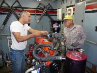 The PES intake is pictured. It will accept a standard Holley carb bolted directly to it. The runners are smaller than a Clifford, but are much more of a direct shot to the carb. The port entry to the head is short compared to a Clifford. Larry is correct, they like less jetting. We will try this again on the 250 dyno tests. Larry, do you want to prep a "194" head to be tested on the 250? I would certainly run it. Or even a open chamber head? Or anyone else? Here is a neat article about relying on flow bench readings. Interesting read. http://www.rehermorrison.com/blog/?p=275
Inliner Member 1716 65 Chevelle Wagon and 41 Hudson Pickup Information and parts www.12bolt.com
|
|
|
|
|
Joined: Jul 2000
Posts: 4,585 Likes: 19
1000 Post Club
|
|
1000 Post Club
Joined: Jul 2000
Posts: 4,585 Likes: 19 |
There was or is another article out there pretty much just like that one and I have read both a few years ago. And they are right.And yeah Tom Langdon on the right and the saw guy on the left.lol
Larry/Twisted6 [oooooo] Adding CFM adds boost God doesn't like ugly.
|
|
|
|
|
Joined: Aug 2003
Posts: 1,905
1000 Post Club
|
|
1000 Post Club
Joined: Aug 2003
Posts: 1,905 |
I know nothing about performing a dyno test. Why is necessary to have such a large air horn on the carb?
Drew
Mid-Atlantic Chapter
|
|
|
|
|
Joined: Oct 2007
Posts: 5,015 Likes: 47
1000 Post Club
|
|
1000 Post Club
Joined: Oct 2007
Posts: 5,015 Likes: 47 |
"The Saw Guy" now thats funny I don't care who you are! Tom, I think you have a new handle. That's like calling Truman "Margaret's Dad." Larry cut to the quick with that, pun intended. Always, I mean ALWAYS refer to people by the least of their accomplishments and you'll get a rise and the innuendo is never lost. Thanks Twisted you made my morning.  Sorry Tom but it is funny. Beater
"I wonder if God created man because he was disappointed in the monkey?" Mark Twain
|
|
|
|
|
Joined: Jul 2004
Posts: 365
Contributor
|
|
Contributor
Joined: Jul 2004
Posts: 365 |
To find out what kind of valve to cylinder clearance we had, I did a little experiment. I cut a 3 7/8th inch circle from construction board and centered it over a cylinder on the block. Using a ball peen hammer, the head bolts holes were cut out. This was laid over the head and the area where the cylinder head overlapped the block was marked with whiteout. 1.94 intake and 1.625 exhaust valves were put in @ 1/2 inch lift. As you can see, a 1/16th drill bit would not fit between the valve and the cylinder. a 5/64th bit would just fit on the exhaust side. This is shrouding! 
Last edited by Armond, II#298; 12/18/09 06:18 PM.
|
|
|
|
|
Joined: Aug 2006
Posts: 232
Contributor
|
|
Contributor
Joined: Aug 2006
Posts: 232 |
Armond, how far apart are the axis of the valve centerlines and the cylinder bore centerlines?
To experienced others:
Is this alignment typical of the 230/250/292 engines? Can the bores for the cylinder head bolts be elongated some for better alignment by shifting the cylinder head, bringing the cylinder head down relative to the construction paper bore (as shown in the photo)? This would allow better combustion chamber shaping also.
Last edited by Winter; 12/18/09 07:32 PM.
|
|
|
|
|
Joined: Sep 2008
Posts: 3,669 Likes: 42
1000 Post Club
|
|
1000 Post Club
Joined: Sep 2008
Posts: 3,669 Likes: 42 |
The best method for chamber shaping and relieving, should involve placing the cylinder head onto the blocks deck surface, and then securing it with a couple of head bolts. Then flip the block upside down, and reaching down the cylinders, scribe the cylinders outline onto the heads deck surface. Once the head is removed, you can unshroud the chamber to this point around the valves as needed to further enhance its breathing. This method will guarantee that each chamber is unshrouded to each specific cylinder it will interact with regardless of any core shift in either the block or the head. Elongating the bolt holes wont allow the head to move, because it has dowels that locate it.
Class III CNC Machinist/Programmer
|
|
|
|
|
Joined: Jul 2004
Posts: 365
Contributor
|
|
Contributor
Joined: Jul 2004
Posts: 365 |
If you look very closely at the picture, you can see the scribe mark I made by placing the head on the block and scribing the head. This is where the cylinders mate with the head. Moving the head over 5/16th on the block would center the valves and combustion chamber. It seems like a lot of work to get every thing to match up (dowels, push rods, water holes).
|
|
|
|
|
Joined: Jun 2007
Posts: 1,411
1000 Post Club
|
|
1000 Post Club
Joined: Jun 2007
Posts: 1,411 |
That's a good point about the dowels, I would prefer to retain some sort of positive location on the head if I were playing with that, so I wouldn't want to omit them from a runnable engine.
However, if one were to plug those holes and re-drill them elsewhere, AAANNND deal with pushrod clearance is it possible to move the head over the 3/8" or so to center the valves over the bore without spraying water everywhere? (also without welding on the head or block)
I am asking as there appears to be an extra 1/8" of valve to bore clearance if they were centered, that could (maybe) get enough material to unshroud the valves without a bore relief.
My, what a steep learning curve. Erik II#5155
|
|
|
|
|
Joined: Sep 2008
Posts: 3,669 Likes: 42
1000 Post Club
|
|
1000 Post Club
Joined: Sep 2008
Posts: 3,669 Likes: 42 |
Nex, you are absolutely right. Im sure everyone knows that offset head dowels are available for the SBC and BBC engines, as well as others, so im sure there would be benefits to shifting the head to help this problem on these engines. You just need to find a compromise between keeping the additional grinding and clearancing for pushrods and water passages covered to a comfortable "happy medium", so it will be a benefit instead of just an exercise in futility. Im sure it could be helpful to try it, and might even see some surprising results from it.
Class III CNC Machinist/Programmer
|
|
|
|
|
Joined: Jul 2000
Posts: 4,585 Likes: 19
1000 Post Club
|
|
1000 Post Club
Joined: Jul 2000
Posts: 4,585 Likes: 19 |
Many have done this along with milling the head on a angle.
milling/shaving more off the plug side of the head.
Larry/Twisted6 [oooooo] Adding CFM adds boost God doesn't like ugly.
|
|
|
|
|
Joined: Apr 2004
Posts: 3,556 Likes: 35
1000 Post Club
|
|
OP
1000 Post Club
Joined: Apr 2004
Posts: 3,556 Likes: 35 |
To move the head 1/8" would be fairly easy, farther than that lots of things will come into play.
The first 1/8" would involve simple elongating of:
Head bolt holes
push rod holes
Some allining of water and oil drain backs and the dowel pins.
To go farther than a 1/4" will get the cylinder close to the head water passage between pushrods. And the bolt boss in the siamesed port will get thin and close to water.
It may be way easier to just relieve the block. I do have a bad 250 that can be cut up. That way thickness's can be checked at top of cylinders for relieving.
Armond, Nice pic! Good showing of a bad chamber design to go over the block. Tom
Inliner Member 1716 65 Chevelle Wagon and 41 Hudson Pickup Information and parts www.12bolt.com
|
|
|
|
|
Joined: Aug 2006
Posts: 232
Contributor
|
|
Contributor
Joined: Aug 2006
Posts: 232 |
Alignment of the cylinder head is a concern for two reasons related to air flow around the intake valve.
1) Centering the valves in the bore will help unshroud the valves around the sides. Centering will also reduce or alleviate the ridge formed by the combustion chamber extending beyond the cylinder wall.
2)The area above the intake valve in the photo (spark plug side of the combustion chamber) is the high flow side of the valve. This area is very important for unshrouding and blending for good air flow. As shown in the photo, the size of this area has been reduced by placing the valve center line above the cylinder bore centers. Positioning the valves centers above the bore center line as has been done is more disadvantageous for good air flow than positioning the valve centers below the bore center line. Relocating the cylinder head on the block would be a pain. Significant performance increase may result, so that's why I asked. And, I agree with the statements above by others on the compromises to be evaluated concerning effort, cost, and performance results.
Larry (Twisted Six), as you stated that this has been performed in the past, do you recall the performance results of centering the cylinder head in the cylinder bore?
|
|
|
|
|
Joined: Jun 2007
Posts: 1,411
1000 Post Club
|
|
1000 Post Club
Joined: Jun 2007
Posts: 1,411 |
1/4" is the practical "easy" limit?
Good to know, thank you all.
I thought maybe I was seeing things, again.
My, what a steep learning curve. Erik II#5155
|
|
|
|
|
Joined: Sep 2008
Posts: 3,669 Likes: 42
1000 Post Club
|
|
1000 Post Club
Joined: Sep 2008
Posts: 3,669 Likes: 42 |
Winter, we also experimented with moving to cylinder head around on the deck surface. We did see some negligable gains, but found that just unshrouding the chamber was the best and most effective way to get bigger gains. I know of several top Comp Eliminator racers that today currently have even moved the intake valve centerlines away from the bore toward the exhaust valve, and have gotten the same results as if they unshrouded the chamber with the valve in the stock location. They are currently using a 21 cc chamber that was been completely redesigned and reshaped. Also long gone are the familiar lump style intake ports, this has been abandoned almost 10 years ago by most all of the top frontrunners still using the siamese heads in professional racing, in favor of more modern technologies, and are experiencing intake ports with flow #'s over 400 CFM. Thats pretty amazing, since the Ford guys are allowed to use the AJ Billet head for their engines, and thats about the same flow #'s they are getting from them, so its pretty cool, that a 30+ year old head casting can perform closely to a state of the art billet head. I think you can see that even the chamber itself still needs to be unshrouded when using big valves, and that just moving the head around by itself doesn't eliminate or correct that, it only corrects the cylinder shrouding which is a different issue. When using a 2.150" intake valve as we did, you have to notch the top of the cylinder to unshroud it. It also is helpful to do this on smaller valves also, especially if you don't have a big cylinder overbore.
Class III CNC Machinist/Programmer
|
|
|
|
|
Joined: Aug 2006
Posts: 232
Contributor
|
|
Contributor
Joined: Aug 2006
Posts: 232 |
CNC-Dude, thanks for the information. Are your references of examples specifically from Chevrolet 194/230/250/292 cylinder heads (except for the Ford head comment) or for other type cylinder heads as well?
|
|
|
|
|
Joined: Sep 2008
Posts: 3,669 Likes: 42
1000 Post Club
|
|
1000 Post Club
Joined: Sep 2008
Posts: 3,669 Likes: 42 |
Winter, yes this info is specifically for the siamese port heads only.
Class III CNC Machinist/Programmer
|
|
|
|
|
Joined: Jul 2002
Posts: 37
Active BB Member
|
|
Active BB Member
Joined: Jul 2002
Posts: 37 |
Scott - In response to your post, having been out of NHRA racing for several years, I wasn't aware that there were any competitive Chevy siamese port Comp Eliminator teams still participating. Could you let me know who these teams are, especially the one producing air flow numbers over 400 cfm. I'd like to contact them to get some technical information on their cylinder heads.
Thanks,
Bob
|
|
|
|
|
Joined: Sep 2008
Posts: 3,669 Likes: 42
1000 Post Club
|
|
1000 Post Club
Joined: Sep 2008
Posts: 3,669 Likes: 42 |
Your right, there are very few currently still using the siamese headed engines. Its doubtful they will even discuss it with you because the world of Comp and most Pro classes is very secretive, just like Nascar or any other class that relys on speed secrets to gain an edge.
Class III CNC Machinist/Programmer
|
|
|
|
|
Joined: Apr 2007
Posts: 92
Active BB Member
|
|
Active BB Member
Joined: Apr 2007
Posts: 92 |
Scott do you think those guys use a surface model for combustion chamber geometry and is touching up the combustion chamber with a ball mill something not even they would bother with? In my world Im only firing on all cylinders when handwork has been reduced to zero and unshrouding/chamber shaping are going to be requirements in the older head so this topic relates well. Has anyone tried a helical trench, bulge, or other geometry on the tight side rather than just blending up to a scribe mark and/or automated the shaping process for consistency and finish? I would have thought that proven chamber designs would be out there with the huge following behind these engines. 
1952 Chev 1300 Cdn. ½ ton
|
|
|
|
|
Joined: Apr 2004
Posts: 3,556 Likes: 35
1000 Post Club
|
|
OP
1000 Post Club
Joined: Apr 2004
Posts: 3,556 Likes: 35 |
Finally got #'s back from the flow bench testing of the 2 different heads being discussed. Both heads have the same amount of machining, porting, HI-FLOW lumps and valve sizes being 1.94/ 1.60. Both heads also had a cutter used to remove material in the chamber to give appr .150 clearance to the chamber wall. 1st head is the "194" head. 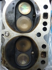 Lift Flow CFM .100 59.4 .200 117.8 .300 161.9 .400 192 .500 213.9 .600 227.3 This is the open chamber head  Lift Flow .100 60.9 .200 118.6 .300 176.5 .400 211 .500 231.8 .600 246.1 As can be seen here , the open chamber head clearly outflowed the closed chamber head with the same modifications done. If someone were to spend countless hours opening the chamber on the "194" head, then flow would certainly improve. This is not what the average Guy will want to do for a street engine. When these exact same heads were tested on the dyno 292, the "194" head was down on power compared to the open chamber head. Even with the increase of compression help the "194" head, tq was down across the rpm range. A 1.84 intake valve could be tried in the "194" head. From prior flow testing and dyno testing of the 1.84 valved open chamber head, also on the 292 mule, power was down and was nearly equal to the 1.94 "194" head. Tom
Last edited by tlowe #1716; 01/09/10 12:42 PM.
Inliner Member 1716 65 Chevelle Wagon and 41 Hudson Pickup Information and parts www.12bolt.com
|
|
|
|
|
Joined: Sep 2004
Posts: 5,839 Likes: 1
1000 Post Club
|
|
1000 Post Club
Joined: Sep 2004
Posts: 5,839 Likes: 1 |
I just can only say again,,,you cannot use a 1.94" intake valve in a 194 head,they cannot flow that way,(unless you modify the chamber greatly) you would need to cut down a 1.94" intake to a smaller size to make it work & be a closer/better comparision.
Valve jobbing is very critical,if one seat is .010 wider on one cylinder head, another head being compared to has a narrower seat, you can loose 10-20 cfm just from that alone.It depends on a lot of factors.
Like I said before,you dont learn this stuff overnight,just in a couple hrs is all it takes, sarcasium, again, sorry.
12 port SDS EFI
|
|
|
|
|
Joined: Nov 2009
Posts: 29
Active BB Member
|
|
Active BB Member
Joined: Nov 2009
Posts: 29 |
I didnt see it maybe I missed it , just curious on what the head cc'd at for the 292? Im currently building a 292 and we went with 70cc per combustion chamber on the head. any info is greatly appreciated..
|
|
|
|
|
Joined: Sep 2008
Posts: 3,669 Likes: 42
1000 Post Club
|
|
1000 Post Club
Joined: Sep 2008
Posts: 3,669 Likes: 42 |
The large chamber heads were 70cc.
Class III CNC Machinist/Programmer
|
|
|
|
|
Joined: Nov 2009
Posts: 29
Active BB Member
|
|
Active BB Member
Joined: Nov 2009
Posts: 29 |
thanks for the info thats what I went with ..
|
|
|
|
1 members (stock49),
161
guests, and
42
robots. |
|
Key:
Admin,
Global Mod,
Mod
|
|
|
|