|
|
Joined: Nov 2004
Posts: 1,805 Likes: 1
1000 Post Club
|
OP

1000 Post Club
Joined: Nov 2004
Posts: 1,805 Likes: 1 |
Though I'd break this out on a new thread. LONG POST
A few basics... In the land of Megasquirt (MS) there are 2 separate software development projects. The basic MS code that is written by Bowling and Grippo the 2 guys that designed the MS. Then there is the MSExtra code development.
Basically Bowling & Grippo bring the technology to life, then the MSExtra guys take Grippo's software and get different cars running on it. They do this by adding a lot of different features like different crank trigger wheels.
The MSextra software (and its easy to install)uses 3 outputs to fire the 6 coils.
The Chevy inline 6 firing sequence is this (even for the 4200). 153624.
In wasted spark mode the coils are paired as follows:
1&6
5&2
3&4
MS spark output A fires 1&6 together.
MS spark output B fires 5&2 together.
MS spark output C fires 3&4 together.
On #1 compression #6 is on the exhaust stoke with the #6 exhaust valve closing. So when #1 coil fires at say 20* BTDC it lights the mixture. #6 coil also fires at the same time as #1, but since there is only exhaust gas in the cylinder nothing bad happens. Then later when #6 is on compression #1 is on exhaust.
The same happens for the other 4 cylinders just 120* and 240* apart from 1&6.
A little info on the trigger wheels. When someone refers to say 36-1 trigger wheel what they mean is this:
36 is the total number of possible teeth on the trigger wheel.
the -1 is the number of missing teeth.
Why do we need a missing tooth ? This is how the software figures out where the crankshaft is in relation to #1 TDC. When a system is installed you mechanically measure using a degree wheel where TDC is. Then measure at what crankshaft angle before #1 TDC the missing tooth is (to the center of the missing tooth) )as it passes the under center of the crankshaft sensor. The number of degrees is entered into the tuning software that runs on a PC usually a laptop, then its programmed into the MS box by pressing 1 s/w button just like the "submit" button to send this message. Its not hard.
The 250/292 (maybe even the early 235/261 I don't know these well) would be a real easy conversion to crank trigger using a 36-1 trigger wheel off of a '90 - '97ish Ford escort (1000's of these in the junkyards) and the crank trigger sensor. What makes it easy is there is nothing mounted to the front of the damper! With a little lathe work to make a centering hub - adapt the escort wheel to the 250 damper. Then make a bracket to hold the crank trigger so its in the same relation to the trigger wheel as it was on the donor vehicle. If the coils are directly fired from MS then the crank trigger can be mounted on the passenger side of the crank and the bracket does not have to have any timing adjustment but needs an adjustment to set the air gap between the end of the sensor and the timing wheel - typica;; 0.035" to 0.04" air gap. When you mount the trigger wheel set the motor say at 35* BTDC #1 using a degree wheel. Then center the missing tooth under the crankshaft sensor. Double check the angle and enter it into the s/w.
Once the engine is running you can make set the base timing (just like setting a distributor with the vacuum hose un-plugged) in s/w check the timing with your timing light. This allow you to correct any timing errors.
Then once the base timing is set you enter the timing advance curve into the tuning s/w. This is akin to setting your mechanical advance curve using springs/weights and the vacuum advance by changing the restriction in the vacuum advance pot and its spring tension. Except its a lot more accurate and adjustable.
The ignition coils off of a LS series motor would work really well on an earlier inline 6 since each coil has a short plug wire on it. The coils could be mounted on top of the valve cover or off a cool side cover mount as long as the spark plug wires is long enough mount them anywhere.
As far as sensors go to do this you would need a MAP sensor, crank trigger sensor, and a coolant temperature sensor. All these can be found in the junkyard for cheap.
When I harvest sensors I grab as much of the connecting wire and the connector as I can get off. Its easy to trim the excess later but a pain to splice especially for the crank trigger since they typically use a shielded wire.
Ok now your wonder why in the world would I want to do all this work?
1) dead nuts exact timing for each cylinder - its accurate within 0.05 degrees.
2) Much higher spark output - each coil only fires 1/3 as often as a distributor coil which fires each time a cylinder needs to fire. This allow much better energy build up in the coil and a way hotter spark.
3) There is no rotor/distributor cap air gap to jump across which causes a lot of electrical noise and spark loss - when the distributor advances the timing the rotor moves out of phase with the distributor cap contact making the spark energy jump further to get across the gap. Also there is no cap/rotor to wear out or carbon track (ugggghh ! I almost froze one winter on my old 250 when this happened - it was -35 out).
4) Better mileage and performance, typically folks find 10-15 HP on a 200HP motor when they convert.
5)Each spark plug wire is the same length - each cylinder gets the same spark energy.
6) much easier starting - just check the video.
7) The attention it would draw.. something truly different.
This ignition setup would work perfectly well with a carb'ed vehicle. You do not have to hook up the injectors to get the ignition working, MS does not care if there are no injectors connected. If/when you want to convert to fuel injection its just installing the injectors/fuel system and running a few wires. If you installed a wideband O2 sensor then you could data log how well tuned your carb is... maybe fine some mileage/performance out that fuel leaker..
Last edited by efi-diy; 03/03/09 11:09 PM.
51 GMC 4.2 turbo
Can't solved today's problems using the same technology/thinking that created them
|
|
|
|
|
Joined: Oct 2007
Posts: 5,015 Likes: 47
1000 Post Club
|
|
1000 Post Club
Joined: Oct 2007
Posts: 5,015 Likes: 47 |
"I wonder if God created man because he was disappointed in the monkey?" Mark Twain
|
|
|
|
|
Joined: Jun 2007
Posts: 1,411
1000 Post Club
|
|
1000 Post Club
Joined: Jun 2007
Posts: 1,411 |
Thank you Mr. Marc. Might have to retro this onto the Berkeley. 
My, what a steep learning curve. Erik II#5155
|
|
|
|
|
Joined: Jul 2000
Posts: 4,585 Likes: 19
1000 Post Club
|
|
1000 Post Club
Joined: Jul 2000
Posts: 4,585 Likes: 19 |
GREAT INFO 
Larry/Twisted6 [oooooo] Adding CFM adds boost  God doesn't like ugly.
|
|
|
|
|
Joined: Jun 2007
Posts: 1,411
1000 Post Club
|
|
1000 Post Club
Joined: Jun 2007
Posts: 1,411 |
I just had a thought, is that the same # of teeth off the 5.0 Ford V8?
I have one of those (and the sensor) somewhere. I'll have to check.
My, what a steep learning curve. Erik II#5155
|
|
|
|
|
Joined: Nov 2004
Posts: 1,805 Likes: 1
1000 Post Club
|
|
OP
1000 Post Club
Joined: Nov 2004
Posts: 1,805 Likes: 1 |
Chris,
Not sure on the mustang 5.0 as I'm not a ferd type... Ferd did use the 36-1 on just about everything EDIS.
51 GMC 4.2 turbo
Can't solved today's problems using the same technology/thinking that created them
|
|
|
|
|
Joined: Jan 2008
Posts: 48
Active BB Member
|
|
Active BB Member
Joined: Jan 2008
Posts: 48 |
Can anyone post a picture of a harmonic balancer with 36-1 wheel attached? I'm trying to visualize how this would be done. Yes, I did read the entire thread and the info is excellent, but it helps to see things (at least for me). Thanks
|
|
|
|
|
Joined: Oct 2006
Posts: 185
Contributor
|
|
Contributor
Joined: Oct 2006
Posts: 185 |
Bristowbob, email me your email address and I will send you a photo of the EDIS wheel on a straight 8 Buick. My email is garyhartracing@yahoo.com Nevermind, I found your email address and sent you some photos.
Last edited by GH; 02/05/10 11:44 AM.
|
|
|
|
|
Joined: Oct 2000
Posts: 368
Contributor
|
|
Contributor
Joined: Oct 2000
Posts: 368 |
Gary, Why don't you post a photo so we can see it too?
Tim
Tim Tenold
I.I.#498
|
|
|
|
|
Joined: Oct 2006
Posts: 185
Contributor
|
|
Contributor
Joined: Oct 2006
Posts: 185 |
Titen, I'm not computer smart enough to post photos on this site.
|
|
|
|
|
Joined: Jan 2008
Posts: 48
Active BB Member
|
|
Active BB Member
Joined: Jan 2008
Posts: 48 |
"What makes it easy is there is nothing mounted to the front of the damper! With a little lathe work to make a centering hub - adapt the escort wheel to the 250 damper."
This is the part I'm having trouble "seeing". How is the EDIS wheel attached to the damper?
Thanks, Gary, for your email.
|
|
|
|
|
Joined: Nov 2004
Posts: 1,805 Likes: 1
1000 Post Club
|
|
OP
1000 Post Club
Joined: Nov 2004
Posts: 1,805 Likes: 1 |
Make a hub that mounts under the balancer bolt and either keyed or doweled to the balancer so it won't rotate when you tighten up the big bolt.
Or if you have a mill with a dividing head index the timing ring to the balancer and make some standoff's - drill/tap the balancer hub and bolt it on.
51 GMC 4.2 turbo
Can't solved today's problems using the same technology/thinking that created them
|
|
|
|
|
Joined: Jan 2008
Posts: 48
Active BB Member
|
|
Active BB Member
Joined: Jan 2008
Posts: 48 |
If I'm understanding correctly, the EDIS ring will, in fact, mount in front of the damper. Am I right, or am I missing something? It seems this assumes a balancer bolt, as opposed to a press fit balancer, right? When I read this initially, I was thinking you were referring to a way to mount the EDIS ring around the outside of the damper. I think that's where I got confused. Sorry 'bout beating this to death. Just a novice here trying to understand.
|
|
|
|
|
Joined: Jul 2004
Posts: 365
Contributor
|
|
Contributor
Joined: Jul 2004
Posts: 365 |
Here's one way to do it  It bolts to the front of the harmonic damper. A spacer is needed to move it out from the damper and to center it.
Last edited by Armond, II#298; 02/06/10 11:32 AM.
|
|
|
|
|
Joined: Jun 2007
Posts: 1,411
1000 Post Club
|
|
1000 Post Club
Joined: Jun 2007
Posts: 1,411 |
Bob, here's a 5.0 Fod Balancer I bought, because it had the wheel and trigger with it. 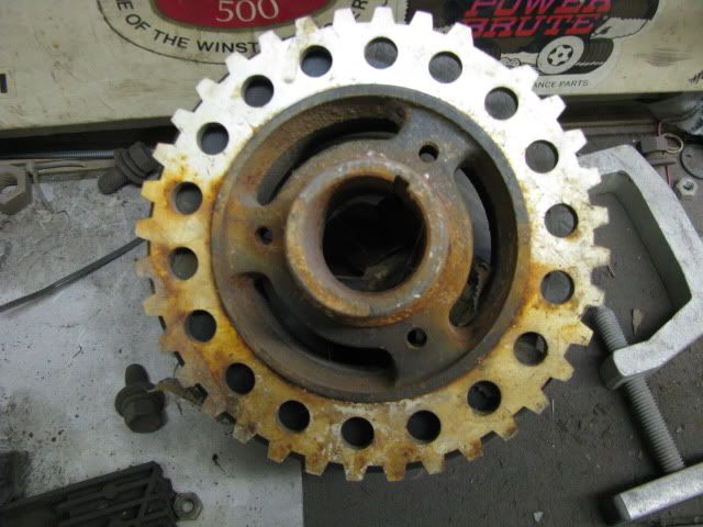 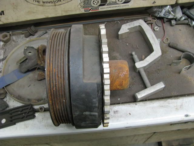 It doesn't appear to be keyed or pinned in any way, just pressed on to a turned down section of the hub. The trigger for the 5.0 is built into the timing pointer (at least this one was).
My, what a steep learning curve. Erik II#5155
|
|
|
|
|
Joined: Jun 2007
Posts: 1,411
1000 Post Club
|
|
1000 Post Club
Joined: Jun 2007
Posts: 1,411 |
Err, make that "FORD" (doh, my proofreader is aparently on break  ).
My, what a steep learning curve. Erik II#5155
|
|
|
|
|
Joined: Jan 2008
Posts: 48
Active BB Member
|
|
Active BB Member
Joined: Jan 2008
Posts: 48 |
Thanks, guys. I think this slow old brain of mine is now on track. Pics always help. Very clean setup, Armond!!
|
|
|
|
1 members (41 Coupe),
334
guests, and
55
robots. |
|
Key:
Admin,
Global Mod,
Mod
|
|
|
|