|
|
Joined: May 2009
Posts: 493
Contributor
|
OP

Contributor
Joined: May 2009
Posts: 493 |
Last edited by strokersix; 12/22/10 12:15 PM.
|
|
|
|
|
Joined: Apr 2004
Posts: 3,556 Likes: 35
1000 Post Club
|
|
1000 Post Club
Joined: Apr 2004
Posts: 3,556 Likes: 35 |
Sounds like a weight reduction plan. Bet it gets better mileage when you are done.
Inliner Member 1716 65 Chevelle Wagon and 41 Hudson Pickup Information and parts www.12bolt.com
|
|
|
|
|
Joined: Oct 2007
Posts: 5,015 Likes: 47
1000 Post Club
|
|
1000 Post Club
Joined: Oct 2007
Posts: 5,015 Likes: 47 |
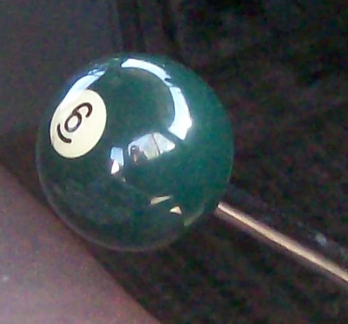
Way back then a lot of us ran 6s because that is what the car came with. We made the best of it and even got good enough at it that we took pride in our inlines. Pulling a V8, especially a BBC, to install a straight 6 is just about as far as you can go to make our point. Do you think there is something wrong with us?  
"I wonder if God created man because he was disappointed in the monkey?" Mark Twain
|
|
|
|
|
Joined: May 2009
Posts: 493
Contributor
|
|
OP
Contributor
Joined: May 2009
Posts: 493 |
|
|
|
|
|
Joined: Apr 2003
Posts: 1,537 Likes: 15
1000 Post Club
|

1000 Post Club
Joined: Apr 2003
Posts: 1,537 Likes: 15 |
Nice carving job on that now ex-double-sink . . . 
|
|
|
|
|
Joined: Apr 2010
Posts: 106
Contributor
|
|
Contributor
Joined: Apr 2010
Posts: 106 |
Awesome parts washer! I saved an old stainless steel counter top with built in sink to make into a parts washer, don't think mine is gonna be long enough for inline 6 parts like that though, it's just a single well!
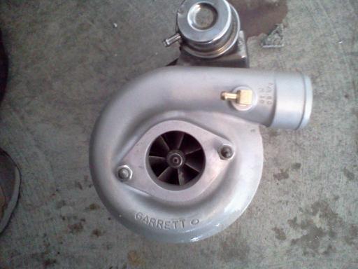
".....don't give up a TURBO more than makes up for all of this BS." Turbo-6
|
|
|
|
|
Joined: May 2009
Posts: 493
Contributor
|
|
OP
Contributor
Joined: May 2009
Posts: 493 |
|
|
|
|
|
Joined: Sep 2004
Posts: 5,839 Likes: 1
1000 Post Club
|
|
1000 Post Club
Joined: Sep 2004
Posts: 5,839 Likes: 1 |
strokersix,
just curious as to how you got to the that stroke dimension?
What length rods etc.
I would like a stoke of 3.75 or so myself.
292 crank has a 2.1" rod journal? Turn it down .100" = 2.00" or?
Thanks
MBHD
12 port SDS EFI 
|
|
|
|
|
Joined: Apr 2004
Posts: 3,556 Likes: 35
1000 Post Club
|
|
1000 Post Club
Joined: Apr 2004
Posts: 3,556 Likes: 35 |
I'd like to see you have a lift around .510 or so. The short duration is fine, but that also limits the amount of lift that can be had. The bolt in lumps help the most with flow above .3 of lift.
The full length headers will work the best for tq.
Inliner Member 1716 65 Chevelle Wagon and 41 Hudson Pickup Information and parts www.12bolt.com
|
|
|
|
|
Joined: May 2009
Posts: 493
Contributor
|
|
OP
Contributor
Joined: May 2009
Posts: 493 |
It's a modified 12 weight 292 crank. Destroked to 4.062, 2.00 crankpin, 6.0 rod length. Block is an '80 vintage 250.
I used the same crank in a previous build with 5.7 rods and 4.000 bore 383 v8 Chevy pistons so the crank has plenty of clearance to the wristpins.
This build has longer rods (r/s ratio), smaller bore (thicker cylinder walls), and lump ports (more flow) so should be better all around. And if it runs on 87 octane that's not a bad thing in my mind. We'll see.
tlowe or anyone: I have some $$ left in the budget for this build and would love to try a roller cam. Any suggestions?
Last edited by strokersix; 12/28/10 12:42 AM.
|
|
|
|
|
Joined: Sep 2004
Posts: 5,839 Likes: 1
1000 Post Club
|
|
1000 Post Club
Joined: Sep 2004
Posts: 5,839 Likes: 1 |
Do you want to run a hyd or solid roller cam?
MBHD
12 port SDS EFI
|
|
|
|
|
Joined: May 2009
Posts: 493
Contributor
|
|
OP
Contributor
Joined: May 2009
Posts: 493 |
I don't have any experience with roller cams. What are the trade offs between hydraulic and solid in a mild application like this?
Periodic lash adjustment with a solid is not a problem for me.
Is a rev kit required to maintain roller contact?
|
|
|
|
|
Joined: Sep 2004
Posts: 5,839 Likes: 1
1000 Post Club
|
|
1000 Post Club
Joined: Sep 2004
Posts: 5,839 Likes: 1 |
Need to know a few things.
Weight of vehicle, trans,manual, auto,if auto what stall on the converter?
Total displacement of engine.
Rear end gear ratio.
Daily driver w/good mileage?
Street/ocational strip/track times.?
Want just maninly low end & mid range?
And so-on.
I am not thinking you need a rev kit for a low comp/rpm engine.
A small roller solid cam is fine w/no rev kit or stud girdle.
MBHD
MBHD
12 port SDS EFI
|
|
|
|
|
Joined: May 2009
Posts: 493
Contributor
|
|
OP
Contributor
Joined: May 2009
Posts: 493 |
Weight: It's a '72 Nova with all factory hardware and full interior, no A/C. I haven't had it on a scale but let's call it 3200 lbs.
Drivetrain: M20 wide ratio Muncie, 3.08 posi rear, 24.5 inch tall tires
Displacement: 296 in^3
Not a daily driver. However, I do want it to run comfortably with good fuel economy on the highway for short road trips. Occasional full throttle blast just for fun is desireable (of course!) but not primary goal.
Small solid roller sounds like what I need. I was happy with the Comp 252 performance last build (252 dur @.006, 206 dur @.050, .474 lift). How about same seat timing with more .050 and more lift? Call it 252 dur @.006, 212 dur @.050, .510 lift might do well.
Last edited by strokersix; 12/28/10 10:07 PM.
|
|
|
|
|
Joined: Apr 2004
Posts: 3,556 Likes: 35
1000 Post Club
|
|
1000 Post Club
Joined: Apr 2004
Posts: 3,556 Likes: 35 |
Remember when figuring solid lift cams, figure in the lash. To net .510 you will need about .530 gross lift.
Depending on how agressive the ramp can be, a 220 dur @ .050 might be attained. That is something to find out from a cam grinder.
The valve springs will need to reset up again with the solid roller inthought. Not a biggie.
Inliner Member 1716 65 Chevelle Wagon and 41 Hudson Pickup Information and parts www.12bolt.com
|
|
|
|
|
Joined: Sep 2004
Posts: 5,839 Likes: 1
1000 Post Club
|
|
1000 Post Club
Joined: Sep 2004
Posts: 5,839 Likes: 1 |
Maybe something like this from Comp Cams
Lift is a bit high ,but they should be able to provide less lift from there master cam profile catalog.
Solid roller
LOBE RATED DURATION IN LOBE TAPPET LIFT @ THEORETICAL VALVE LIFT
NUMBER DURATION DEGREES LIFT TDC @ 0 LASH ROCKER ARM RATIO
CAMSHAFT TYPE
@ .050 @ .200 106° 110° 1.5 1.6 1.7
4870 256XSR 218 141 .360 .056 .045 .540 .576 .612
MBHD
12 port SDS EFI
|
|
|
|
|
Joined: May 2009
Posts: 493
Contributor
|
|
OP
Contributor
Joined: May 2009
Posts: 493 |
Thank you guys for your comments.
I will continue to post progress which may be infrequent as I go back to work Monday. Doesn't mean I've abandoned the project, just that progress is slow at times. I purchased the JE pistons more than 10 years ago! I hope to have the Nova running this summer. We'll see.
|
|
|
|
|
Joined: Sep 2008
Posts: 3,669 Likes: 42
1000 Post Club
|
|
1000 Post Club
Joined: Sep 2008
Posts: 3,669 Likes: 42 |
Where on the piston are you checking to see that it .005 out of the hole?
Class III CNC Machinist/Programmer
|
|
|
|
|
Joined: May 2009
Posts: 493
Contributor
|
|
OP
Contributor
Joined: May 2009
Posts: 493 |
Along the bore centerline (above wrist pin) will eliminate piston rock affecting the measurement if I understand what you are asking.
Test fit showed zero deck so I cut .005 to true it all up and give me .005 out of the hole.
Last edited by strokersix; 01/24/11 09:22 PM.
|
|
|
|
|
Joined: Sep 2008
Posts: 3,669 Likes: 42
1000 Post Club
|
|
1000 Post Club
Joined: Sep 2008
Posts: 3,669 Likes: 42 |
Actually along the quench and spark plug side of the pistons are the more critical areas to check the deck, because the piston does rock as the engine is running. I have seen engines with less than .040 piston to head clearance have the pistons bump the head. The way you are measuring it, the piston can rock .010 to .015 more out of the bore at these points and cause you problems. It also increases with more piston to cylinder wall clearance, so this should be checked after the block is finish honed to ensure a more accurate reading.
Class III CNC Machinist/Programmer
|
|
|
|
|
Joined: May 2009
Posts: 493
Contributor
|
|
OP
Contributor
Joined: May 2009
Posts: 493 |
Understood.
But seems to me the piston rocking will be dependent on piston and block temperature. Checking cold probably worse than when running. I would expect less bore clearance and less rock at operating temperature. But that's just a guess without knowing exactly how the piston will expand. I've read that piston geometry is specifically designed to match piston and block thermal expansion even though it's aluminum versus cast iron. In my case, I have no way of knowing and have to hope that JE did a good job with my pistons.
Are you suggesting piston/head distance of .035 (.040 gasket -.005 out of hole, not counting piston rocking) isn't enough? I'm going for high squish velocity and as much compression as I can get. If I find evidence of contact I can always trim a bit off my pistons.
Last edited by strokersix; 01/24/11 09:51 PM.
|
|
|
|
|
Joined: Sep 2008
Posts: 3,669 Likes: 42
1000 Post Club
|
|
1000 Post Club
Joined: Sep 2008
Posts: 3,669 Likes: 42 |
If your intention is to gain the best quench you can, it would make sense to check your piston at the quench spots, not in the center of the bore where the chamber is above the piston. Once you bring your piston to TDC, move your indicator to the quench sides of the piston near the edge and rock it inward and outward. This will give you some idea of how much rocking goes on inside the engine. You will see that it is sticking out of the bore a lot more than just .005 at these points. Yes, I have seen pistons hit the head with less than .040(true quench). Don't be afraid to really push on the piston as hard as you can to simulate the rocking, you still cant push it hard enough to match how much the connecting rod rocks it, but you will be safer in making your measurements there. Also, even at an idle with the engine running, the pistons go past TDC 10 to 15 times per second, so by the time you hear a problem it will be too late to do anything. At operating speed(6000-7000)RPM, you could take a bearing out or bend rods, collapse pistons with even just a slight bumping of the head. Just be cautious when pushing the clearance that close.
Class III CNC Machinist/Programmer
|
|
|
|
|
Joined: May 2009
Posts: 493
Contributor
|
|
OP
Contributor
Joined: May 2009
Posts: 493 |
I'm torque plate honing next, then I'll do another test fit and check as you suggest.
Remember though, I'm not racing this one. Don't plan to spin much over 5000 rpm. I will pull the head and check for witness marks after breakin.
Hoping to maximize performance with 87 octane, that's why I'm after the squish velocity.
|
|
|
|
|
Joined: Dec 2010
Posts: 18
Active BB Member
|
|
Active BB Member
Joined: Dec 2010
Posts: 18 |
When you did your crank did you narrow the journals for V8 rods, or get standard 6 widths in a 6" rod?
I've been toying with having the crank welded then reground for big journal SBC rods, this would open up a bunch of rod/piston combos. Not sure that the cost of the crank work would not be less than the cost of custom rods, particularly if several combos were to be tried.
Also, why not a hydraulic roller if it's mostly a cruiser? Would get rid of that annoying lash problem....
Last edited by D13; 01/26/11 04:02 PM.
|
|
|
|
|
Joined: May 2009
Posts: 493
Contributor
|
|
OP
Contributor
Joined: May 2009
Posts: 493 |
I bought Crower rods for Chevy six, 6" long. Stock 292 crank has 2.1" journals same as 350 SB. Last build was with 5.7" stock 250 rods. I clearanced the crank by turning it round in my lathe as small as possible. Then set up on my milling machine to roll on the crankpins. Had a bar on the flywheel flange to roll the crank under the milling cutter for final clearance. With 6" rods you might not need to do the second milling operation. Then I had a local shop grind the crankpins to 2.0" and 4.062 stroke. I try to do as much as I can myself but I don't own a crank grinder or balance rig. Yet. I thought about altering SB rods by adding material to the big end. I bucked up for the Crower rods so never tried it. I would avoid welding on the crank. 2.0" crankpins and 4.062 stroke almost clears the fuel pump lobe on a 250 camshaft. Slight grinding on the rod plus reduced fuel pump lobe diameter will clear. I altered the mechanical pump to compensate for the reduced lobe. This won't be required if you use a 292 camshaft and electric fuel pump. I'm going to run the same Comp 252 cam with altered fuel pump lobe to start with. Already own the parts. Then figure out what to do from there. I would like to run a roller, solid or hydraulic. http://i965.photobucket.com/albums/ae131/strokersix/DSCN3295.jpghttp://i965.photobucket.com/albums/ae131/strokersix/DSCN3296.jpg
Last edited by strokersix; 01/26/11 08:09 PM.
|
|
|
|
|
Joined: May 2009
Posts: 493
Contributor
|
|
OP
Contributor
Joined: May 2009
Posts: 493 |
Cleaned up the head bolt threads in the block and installed the torque plate today. I threaded the studs in the same depth as OEM head bolts. The bores were round before I torqued the studs. They pulled to .003, maybe even .004 inch oversize with studs torqued to about 100 lb-ft. I was expecting .001-.002, not .003-.004. I'll never hone a block without a torque plate again. Have to think about this a bit because my bores are already to size and I sure don't want to open them up another .004. Maybe back off the torque to 80 lb-ft, then run the hone in to knock off the high spots rather than all the way round. I feel more comfortable with .001-.002 oversize at the top of the bore. One solution is to bore another block and use the torque plate this time. http://i965.photobucket.com/albums/ae131/strokersix/DSCN3807.jpghttp://i965.photobucket.com/albums/ae131/strokersix/DSCN3812.jpg
Last edited by strokersix; 01/30/11 06:38 PM.
|
|
|
|
|
Joined: Sep 2004
Posts: 5,839 Likes: 1
1000 Post Club
|
|
1000 Post Club
Joined: Sep 2004
Posts: 5,839 Likes: 1 |
Nice.
Who makes that torque plate?
How much piston to wall clearance does it have now?
MBHD
12 port SDS EFI
|
|
|
|
|
Joined: May 2009
Posts: 493
Contributor
|
|
OP
Contributor
Joined: May 2009
Posts: 493 |
Tom loaned the torque plate to me.
Have not measured the pistons yet. JE made them to fit 3.9355 bore per my request which is right about where they are without the torque plate. Need to do some closer measuring and figuring.
I have not posted a project like this before. Everyone gets to see the screwups as well as the success. With over 1000 views it appears there is interest so I'll keep posting.
Last edited by strokersix; 01/30/11 09:20 PM.
|
|
|
|
|
Joined: Nov 2004
Posts: 1,805 Likes: 1
1000 Post Club
|
|
1000 Post Club
Joined: Nov 2004
Posts: 1,805 Likes: 1 |
Nice.
Who makes that torque plate?
MBHD Fairly sure this is the torque plate that I made.... it went south to Tom when he bought my 292 a few years ago...
51 GMC 4.2 turbo
Can't solved today's problems using the same technology/thinking that created them
|
|
|
|
|
Joined: May 2009
Posts: 493
Contributor
|
|
OP
Contributor
Joined: May 2009
Posts: 493 |
|
|
|
|
|
Joined: Apr 2004
Posts: 3,556 Likes: 35
1000 Post Club
|
|
1000 Post Club
Joined: Apr 2004
Posts: 3,556 Likes: 35 |
How far down the bore did the distortion take place? I have found it to go almost 1 inch. That is why rings have a hard time breaking in. They can never quite conform to the square hole.
Inliner Member 1716 65 Chevelle Wagon and 41 Hudson Pickup Information and parts www.12bolt.com
|
|
|
|
|
Joined: Sep 2008
Posts: 3,669 Likes: 42
1000 Post Club
|
|
1000 Post Club
Joined: Sep 2008
Posts: 3,669 Likes: 42 |
It'll be hard to get that out-of-round out without adding some more clearance, just try to keep your hone at the top of the cylinder as much as possible. That's one reason why more people don't use a torque plate, they don't think it makes that much difference. Lightening up on the bolt torque isn't going to stretch them properly, i'd opt for more clearance instead of possible blown head gasket issues.
What kind of ring gap are you looking to run.
Class III CNC Machinist/Programmer
|
|
|
|
|
Joined: Jun 2007
Posts: 1,411
1000 Post Club
|
|
1000 Post Club
Joined: Jun 2007
Posts: 1,411 |
Stroker, what surface finish is that on the deck? 
My, what a steep learning curve. Erik II#5155
|
|
|
|
|
Joined: May 2009
Posts: 493
Contributor
|
|
OP
Contributor
Joined: May 2009
Posts: 493 |
Distortion is down about an inch but I need to do some more measuring.
I plan to use OEM bolts so I need to install them on this torque plate to see if they pull the bore less. If so, then I can back off the stud torque a bit. That's what I meant. I'm not proposing less clamping at assembly, rather less clamping for the honing operation. And I don't think I need to go all the way round. With all the engines out there running with .004 distortion, mine included, surely if I left .001 distortion it must be better. I haven't thought about ring gap yet.
I don't know the surface finish. It's from the fly cutter I posted above then dressed a bit with a file. Measures true, looks and feels good to me.
Last edited by strokersix; 01/31/11 10:13 AM.
|
|
|
|
|
Joined: Aug 2006
Posts: 232
Contributor
|
|
Contributor
Joined: Aug 2006
Posts: 232 |
Another concern when trying to run tight operating bore clearance is thermal distortion. An article in one of the lubrication engineering magazines I receive for work discussed engine bore operating clearances. This article was related to engines achieving very low emmissions and good fuel economy. The article stated that operating bore dimenisions change more due to the thermal stress caused by the coolant temperature increasing and reaching operating temperature than that due to the mechanical stress induced on the block from torquing the cylinder heads.
Setting up a 180 degree F coolant loop (with pump)for an engine block when mounted in a shop boring machine would take a little work. Doing so would be a good learning experience. Effort for results? Also, I wonder what the running versus cold tolerances would be as a final result. An engine has to operate during cold starts with sufficent proper cold clearances before reaching good operating clearances.
Last edited by Winter; 01/31/11 11:57 AM.
|
|
|
|
|
Joined: Sep 2008
Posts: 3,669 Likes: 42
1000 Post Club
|
|
1000 Post Club
Joined: Sep 2008
Posts: 3,669 Likes: 42 |
See how much difference there is in distortion from the fully torqued state compared to the lesser amount you are considering. Also, cast rings will conform and seal to distorted shapes in the bore much easier than a moly ring will, so if you are using moly stlye rings several thousandths of distortion might still be too much for adequate sealing. A moly ring is just more rigid and less flexible than a cast ring is, and they need a more precise bore to ride up and down in....if your running moly rings.
Class III CNC Machinist/Programmer
|
|
|
|
|
Joined: May 2000
Posts: 1,464
1000 Post Club
|
|
1000 Post Club
Joined: May 2000
Posts: 1,464 |
I think moly rings are in fact cast iron, with a thin insert of molybdinum usually applied to the cast iron in the form of a plasma spray. This quote - taken from the following website: http://aapistons.com/index.php?main_page=page&id=2&chapter=106. Molybdenum (Moly) Ring-Cast iron ring which uses a Molybdenum alloy as a face material.
FORD 300 inline six - THE BEST KEPT SECRET IN DRAG RACING!
|
|
|
|
|
Joined: Sep 2008
Posts: 3,669 Likes: 42
1000 Post Club
|
|
1000 Post Club
Joined: Sep 2008
Posts: 3,669 Likes: 42 |
Yep, the moly is a coating on the rings outside edge. Its wear edge is harder than a plain cast ring, and doesn't seat in as fast if the bores are less precisely machined. They also require a much smoother grit stone for finish honing than a cast ring also.
Class III CNC Machinist/Programmer
|
|
|
|
0 members (),
252
guests, and
35
robots. |
|
Key:
Admin,
Global Mod,
Mod
|
|
|
|