|
|
Joined: Dec 2008
Posts: 84
Active BB Member
|
OP

Active BB Member
Joined: Dec 2008
Posts: 84 |
After getting the engine running for the cam break-in, I've started to make a bit of progress on the turbo fitting and installation. 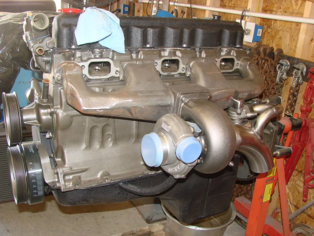 Yes; the blue rag stuffed in the vent hole is a specialty aftermarket part. I would have rather connected the wastegate plumbing further downstream, but I realized that there wasn't going to be any straight exhaust tubing until after the second bend, and so settled for a close-in connection. Intake fitting comes next.
|
|
|
|
|
Joined: Dec 2005
Posts: 452
Contributor
|
|
Contributor
Joined: Dec 2005
Posts: 452 |
Doug, Looks good.
How many inlines running turbos now, going to be a lot of happy Inliners out there!!!
Harry
Turbo-6
|
|
|
|
|
Joined: Jul 2009
Posts: 55
Active BB Member
|
|
Active BB Member
Joined: Jul 2009
Posts: 55 |
|
|
|
|
|
Joined: Jan 2002
Posts: 395
Contributor
|
|
Contributor
Joined: Jan 2002
Posts: 395 |
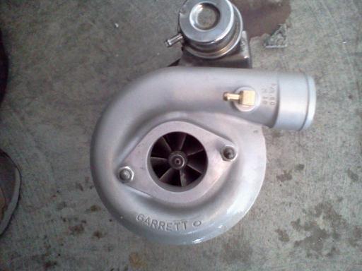
I like this! What turbo is that? Blow though carb setup?
|
|
|
|
|
Joined: Dec 2008
Posts: 84
Active BB Member
|
|
OP
Active BB Member
Joined: Dec 2008
Posts: 84 |
During this last weekend I've fitted the intake and have it installed. I didn't take any pictures as of yet... When I realized that I won't be able to use stock motor mounts, and that to locate the engine to build mounts I would have to put the cab back on the chassis for a while, I decided to go bang my head against another project for a while.
The turbo is a chinese knock-off of a TO4B. 1.15 ratio turbine housing, but the split scroll should make is spool up a bit faster than A/R ratio might imply; the recovery of the pulse energy by keeping the exhaust path separate for each half of the engine is reportedly a good thing.
Intake is a homemade triple TBI set-up using the smaller GM TBIs; 1 3/8" bore if I remember. These have been fitted with teflon seals to prevent throttle shaft leakage.
|
|
|
|
|
Joined: Sep 2008
Posts: 6
Active BB Member
|
|
Active BB Member
Joined: Sep 2008
Posts: 6 |
Will running 3 TBIs solve, or help reduce the problem these engines have with siamesed ports? How's your intake setup going to look? Sounds like the setup to have! Can't wait to hear how it goes.
|
|
|
|
|
Joined: Dec 2008
Posts: 84
Active BB Member
|
|
OP
Active BB Member
Joined: Dec 2008
Posts: 84 |
The charge-robbing due to the siamese ports is exactly what I was working around. The TBI have the injectors above the throttle plates so that at part throttle air mixes with the fuel better. 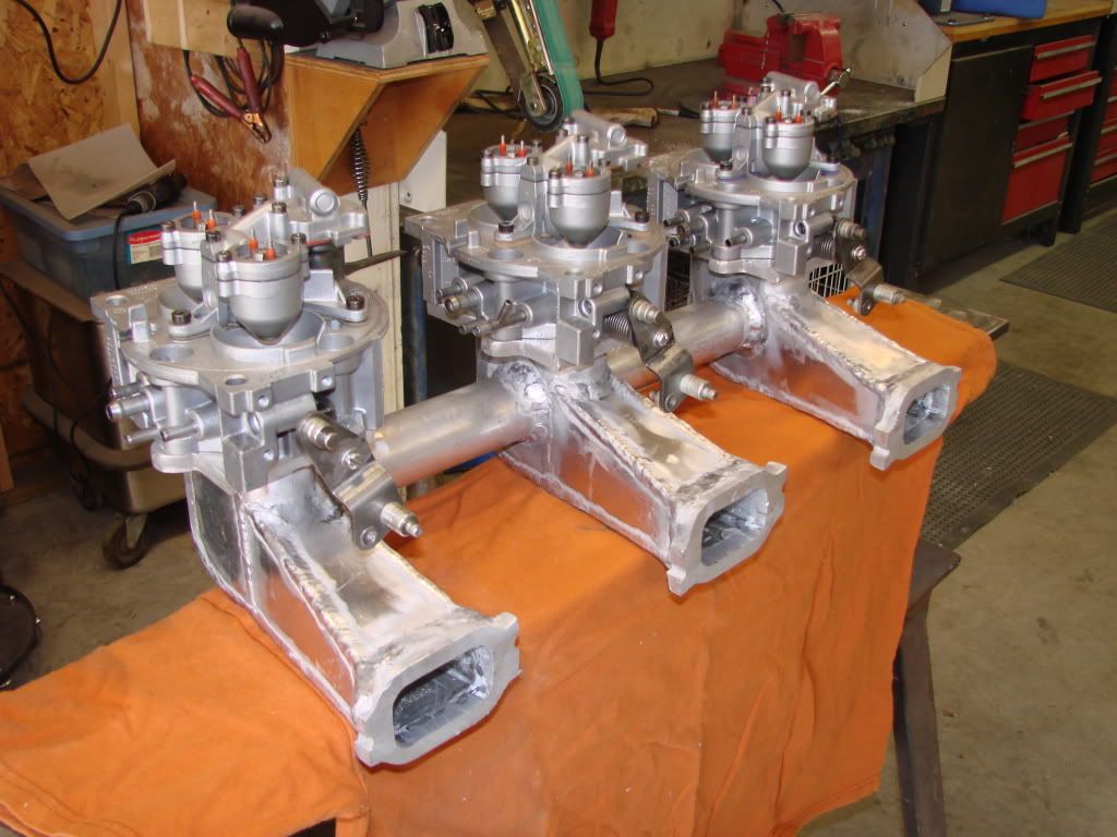 At least in theory, all of the air within the manifolds should be uniformly mixed with fuel, so that the timing of the intake valve events doesn't have the opportunity to pull more or less fuel. This is all pretty crude poor-boy experimentation, so no idea if it will work well. (Or if I'll be able to shut the hood...)
|
|
|
|
|
Joined: Dec 2005
Posts: 452
Contributor
|
|
Contributor
Joined: Dec 2005
Posts: 452 |
Doug, Looks cool,but just like a carb the fuel mix is in the manifold and as the pulses from the intake valves stop and start the fuel may fall out of supension, which makes a temporary lean condition on the other valve in the port. But with your setup one good thing the air pulses will not effect the boosters as with carbs. Good luck.
Harry
Turbo-6
|
|
|
|
|
Joined: May 2000
Posts: 1,464
1000 Post Club
|
|
1000 Post Club
Joined: May 2000
Posts: 1,464 |
I have done some dyno R&D on CFI units. The biggest problem I saw wasn't at idle or WOT - it was when the throttle plates were at NEARLY WOT. At idle the injectors will make a pretty conical spray pattern more or less uniformly distributed across the throttle plate. GOOD.
At WOT the velocity of the inrushing air pulls the conical pattern of the spray discharge down into something more closely associated to the fuel coming out of a carb booster - less conical and less evenly distributed over the cross-sectional area of the throttle bores. Not great, but still GOOD.
BUTT... at throttle blade angles around 75 or 90 degrees the air velocity is large enough to distort the spray discharge from its ideal conical shape. And because the fuel is entering from what is essentially a point source, the injector pintle, and this point source is located directly above the throttle plate, that's when BAD things start to happen. The fuel impinges on the steeply angled throttle plates and "slides" off to one side of the throttle bore, greatly stratifying the fuel mixture and playing havoc with the fuel distribution downstream. I have seen this condition in V8s that exhibited as much as a five air/fuel ratio spread between cylinders. Imagine an engine with 11:1 A/F ratio in one cylinder and 16:1 A/F in an adjacent cylinder!
If I were trying what you are doing I would try to bias this rich / lean condition so that the orientation of the throttle plates serves to offset the latent fuel biasing encountered with siamesed intake runners.
FORD 300 inline six - THE BEST KEPT SECRET IN DRAG RACING!
|
|
|
|
|
Joined: Dec 2008
Posts: 84
Active BB Member
|
|
OP
Active BB Member
Joined: Dec 2008
Posts: 84 |
You guys are right, of course. I was making the mistake of thinking of the fuel charge as entirely evaporated, failing to remember that much of the charge is carried as droplets suspended in air.
I had at one time wondered about the tumble of the air coming through the throttle plates and distortion of the fuel pattern and how those things might affect downstream mixture variations. Without a full-blown computational fluid dynamics modelling suite and a whole lot more knowledge I was forced to put the subject in the category of things-I'm-too-ignorant-to-worry-about.
I had planned to fire the two injectors in each TBI separately, which could have some benefit in time-averaging mixture distribution. The biggest saving grace might be the distance between the throttle plates and the intake valves. In usual central fuel injection set-ups individual intake runners begin at the plenum area a couple of inches below the throttle plates, which would seem to make localized tumble and swirl conditions (with their fuel distribution inequities) strongly influence the mixture being presented at each runner inlet mouth.
What portion of the mixture each cylinder sees is thus effectively "selected" quite near the throttle blades. In the manifold pictured, flows should mix better due to distance and linearization of the streamlines avoiding selection of differentiated portions of the charge. Pulse-induced droplet shake-out could still create some problems however.
Bottom line; I don't know that this will work. I haven't the resources or abilities to do anything exotic, elegant, or well-engineered, but I do want to try something unusual and individual. (Or I'd be working on a belly-button engine...)
I greatly appreciate the applied insight and analysis offered on behalf of my snicker-inducing efforts. I also really appreciate and enjoy the willingness of people with true research and development backgrounds to chat with someone at the hammer and hacksaw level. The odds are that this endeavor will ultimately be relegated to the scrap heap. For me, the fun is in the trying; the faint potential for a triumph just adds savor.
|
|
|
|
|
Joined: Dec 2008
Posts: 84
Active BB Member
|
|
OP
Active BB Member
Joined: Dec 2008
Posts: 84 |
I'm not moving very fast, but I do continue to make minor progress: 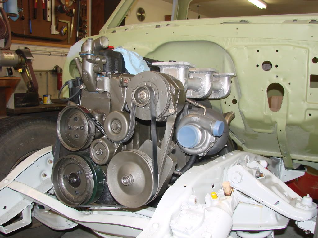 I've gotten the motor mounts fabricated and the accessories installed. The cab is only temporarily sitting on the chassis to check for fit with the drivetrain. Without a heated garage, trying to get the painting done during the winter isn't going to work. To make more room for the turbo, I've moved the engine location an inch to the passenger side: 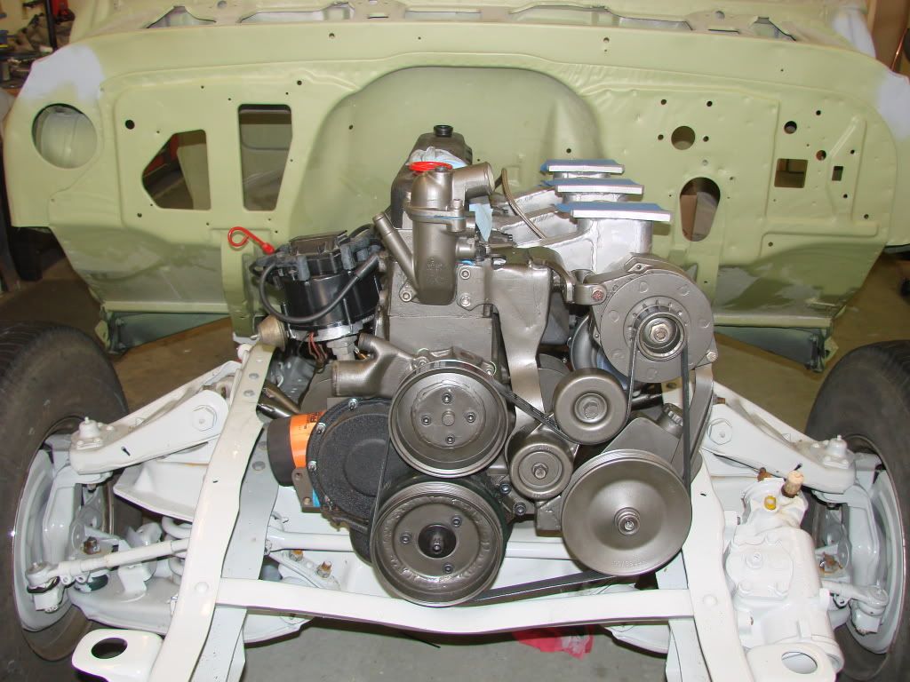 As well as the engine and transmission mounts, I'll eventually also move the driveshaft center bearing supports an inch, which will lessen the amount of offset between the centerline of the engine and the rear axle pinion. I plan to fabricate the remainder of the exhuast system next. And yes; the special aftermarket blue rag has been carefully preserved: 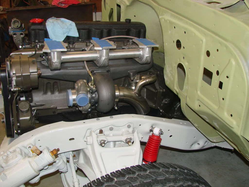
|
|
|
|
|
Joined: Sep 2004
Posts: 5,839 Likes: 1
1000 Post Club
|
|
1000 Post Club
Joined: Sep 2004
Posts: 5,839 Likes: 1 |
Looks good!
Keep up the nice work.
MBHD
12 port SDS EFI 
|
|
|
|
|
Joined: Apr 2010
Posts: 106
Contributor
|
|
Contributor
Joined: Apr 2010
Posts: 106 |
Looks great DougE! LOVE the color of the motor and accessories! Care to share what it is?
".....don't give up a TURBO more than makes up for all of this BS." Turbo-6
|
|
|
|
|
Joined: Dec 2008
Posts: 84
Active BB Member
|
|
OP
Active BB Member
Joined: Dec 2008
Posts: 84 |
It's DupliColor "Cast Iron" engine paint. The sheet metal is black wrinkle powder coat. I've used the color combo before, and it seems to make a nice understated scheme that also works with aluminum.
I actually posted the pictures to see if anyone was interested in the home-made serpentine belt drive system. I couldn't find any sheaves with GM centers of the right diameters, and so transplanted GM centers into Ford sheaves. Quite a trick without a lathe. Brackets are all home blacksmithed.
|
|
|
|
|
Joined: Apr 2010
Posts: 106
Contributor
|
|
Contributor
Joined: Apr 2010
Posts: 106 |
DougE,
Thanks for sharing the color combo! I will be copying that! I had a Shovelhead Harley that I used wrinkle paint on some pieces and left some raw aluminum, I liked the combo....yours looks just as good to me if not better! I dig it!
And as for the serpentine set-up....SUPER SICK! I guess with all the late model stuff being serpentine for quite some time now your set-up snuck past me as it's so common on todays vehicles. That is super cool! I really like subtle custom things that take you a minute to put your finger on and realize what it is. Another idea I will likely copy from you. Hope you don't mind! Immitation is the highest form of flattery ya know!
".....don't give up a TURBO more than makes up for all of this BS." Turbo-6
|
|
|
|
0 members (),
325
guests, and
48
robots. |
|
Key:
Admin,
Global Mod,
Mod
|
|
|
|