logo
12 Port News - Features
12 Port History
Casting Numbers
Online Store
Tech Tips
Become a Member
Previous Thread
Next Thread
Print Thread
Rate Thread
Joined: Apr 2003
Posts: 1,537
Likes: 15
stock49 Offline OP
1000 Post Club
****
OP Offline
1000 Post Club
****
Joined: Apr 2003
Posts: 1,537
Likes: 15
Greetings . . .

The car is back on the road now – though I am sticking close to home during road tests until things are sorted out and I build some trust in car . . .

As I promised in the last status update here’s some details on the last major bit of custom work – the exhaust system.

The stock system consists of just three pieces. The head pipe is 1-7/8” diameter feeding into a conventional 3 tube muffler. The mid+tail pipe is 1-3/4” diameter running from the muffler outlet back to and over the axle eventually exiting straight out beyond the rear bumper. Both the head pipe and tail pipe have a series of crush bends in order to wend their way through the rather congested driver side of a ’49 Chevy.

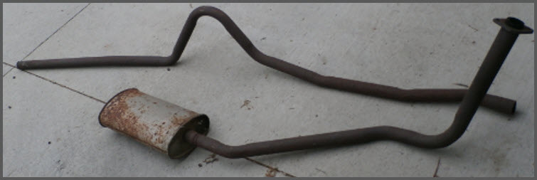
The stock muffler is strategically positioned under the front seat – resting on a single frame mount that provides an aggressive upward angle. The inlet hangs low below the cross-member and frame – but the aggressive angle places the muffler outlet above the frame yet well clear of the floor.

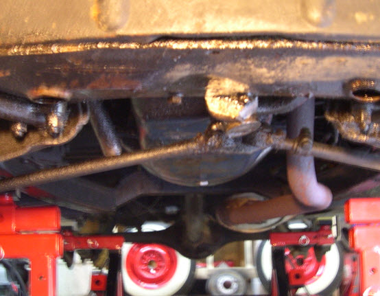
When I fitted the headers during mock-up I puzzled over exhaust system routing immediately. The driver side of a ’49 Chevy is quite busy. There is not much room for a single exhaust pipe let alone two. The stock pipe extends down well below the oil pan – the flange angle essentially providing the ‘first bend’ in the routing. The first crush bend is nearly 90 degrees leading to a short section of pipe that runs straight towards the transmission cross member brace. This first bend is not parallel to the drive line. The second crush bend is in a different plane from the first and is nearly 45 degrees leading to a fairly long section of pipe that parallels the transmission cross member brace – routing the pipe under the cross member and well beyond – essentially taking the pipe back toward the center-line of the car. The third crush bend is another 45 degree turn – in yet another plane – which allows it to mate with the muffler which rests angled upward and back toward the frame.

In the entire system there is only one place where the exhaust pipe routing is parallel to the drive-line – the very last section of tail pipe running next to the gas tank! I knew one thing for sure – I would go insane if I tried to stick build a system that mimicked the stock one . . .

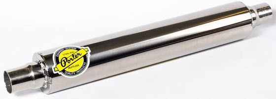
The very first thing I did was to get the mufflers in hand and start working on placement. I went for the original Hollywood muffler – Porters:

The objective was to have the mufflers sitting as far forward as possible – without interfering with the emergency brake linkage – or creating a reflective heat load on the brake lines running along the back of the transmission cross-member. The mufflers ended up very close to where the stock one is located – but they are running parallel to the driveline – sloping up above the level of the frame at a much gentler angle. This gentle angle also provides clearance for the emergency brake cables running directly above the mufflers.

With the mufflers positioned it was clear that the rear-header collector was essentially a straight shot to the driver’s side muffler – albeit with a few bends to clear the emergency brake linkage and the bell-house inspection cover . . . The routing to the passenger side was less obvious. At first I considered going straight back and underneath the rear head pipe – sort of an over-and-under shot gun affair running past the bell-house inspection cover – where there is lots of clearance under the gear box to cross over to the passenger side.

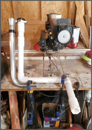
I mocked up this first idea in PVC pipe. The front head-pipe ended up hanging really low beyond the inspection cover – surely a scrape hazard – and it was actually lower than the planned installed height of the mufflers - creating the need for another bend. So I decided instead to go straight down until the pipe was clear of the pan and then 90 degrees straight across to the passenger side – directly under the oil pan.


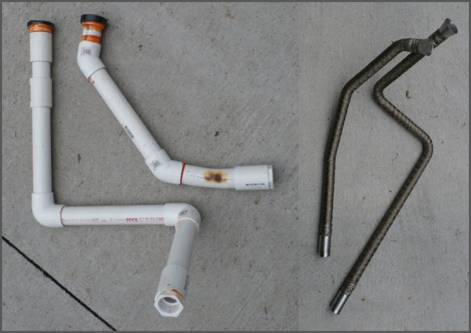
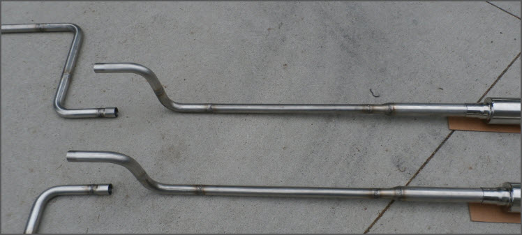
With both pipes mocked up in PVC the basic layout was set. I was then able to order mandrel bends and literally transfer the cut lengths from the PVC template dimensions onto the metal sticks. The bends are made with a short and a long leg. Fit was achieved by simply cutting down either the long or the short leg and then mating with the next stick.

I sent the head pipes off to be welded while I worked on the mid-pipe layout – again with the design principle of straight and parallel to the driveline. Once the head-pipes were back from the welder I was able to final fit them – and determine final length of the straight sections that would mate with the muffler inlets.


The smallest inlet/outlet offered by Porter is 1-3/4” – in spite of the fact that the core of the muffler is just 1-1/2” – with stainless steel wool filling the balance of the 3” housing. On the inlet I used DOM tubing (1.5” ID – 1.75” OD) as a collar over the 1-1/2” head pipes. The collared head pipe extends all the way into the muffler’s inlet resting up against the bulkhead that contains the muffler’s steel packing. The collar is welded only on the very end of the head-pipe (to avoid cracking during heat cycles).

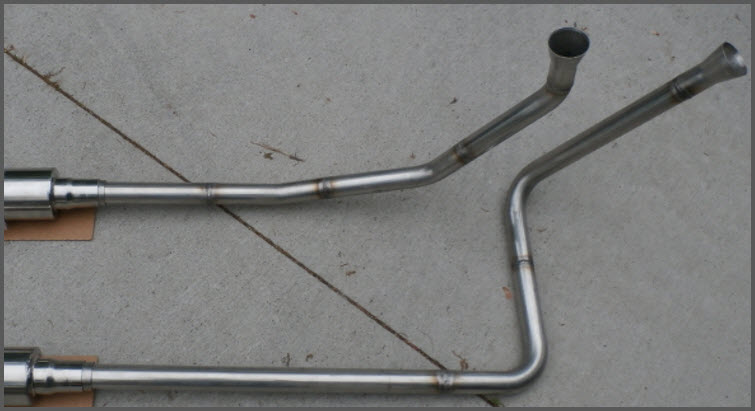
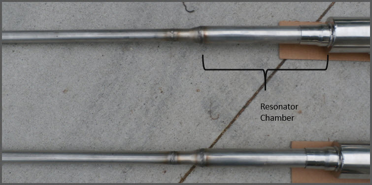
Burns Stainless makes really nice transitions. I used their 2-1/4” to 1-1/2” transitions for the header collectors. The stock Best Gaskets exhaust donuts fit into the large ends nicely. On the outlet side of the muffler I used a 1’ section of straight tube as a resonator chamber followed by a 1-3/4” to 1-1/4” transition down to the 1.25” soda-straw mid-tail-pipes. The transition acts as a reflector sending the raspy tones back toward the muffler. The system exhibits the classic stove-bolt Rap – but it is subdued.


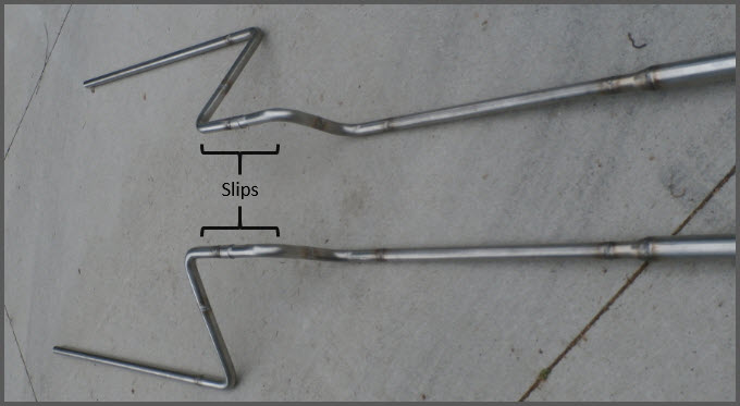
With a slip fit between the mid-pipe and tail-pie – and a slip fit at the muffler outlet I was able to twist/clock the pipes into final position and fit hangers. The passenger side is very tight because of the spare tire well. But the soda straw sized pipe tucks nicely between the spring shackles and the tire well.


By approaching the exhaust design around ‘single plane’ sticks it is easy hand-the-work-off to a professional welder. The welder simply lays the pipe out flat on the welding bench and connects A-to-B-to-C as labeled.


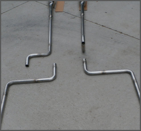
The only exception was the passenger head-pipe – which I witness-marked on the bench directly from the PVC template – the planes are 30 degrees apart.


The mid-pipes and tail-pipes each made two trips to the welder – the first established the length parallel to the drive-line and positioned the first 90 degree elbow. The second trip joined the switch-back legs that run perpendicular to the drive-line.

This is all .065” wall 304 stainless so it should last a good long time . . .

Regards,
Stock49

Joined: Apr 2004
Posts: 3,556
Likes: 35
1000 Post Club
****
Offline
1000 Post Club
****
Joined: Apr 2004
Posts: 3,556
Likes: 35
Nice write up! One big question I have. How does it sound? And what does it look like installed?


Inliner Member 1716
65 Chevelle Wagon and 41 Hudson Pickup
Information and parts www.12bolt.com

Joined: May 2009
Posts: 493
S
Contributor
*****
Offline
Contributor
*****
S
Joined: May 2009
Posts: 493
I too am interested in the sound and if you feel happy with the performance. The small pipes and "resonator chamber", is that known or something new?

Nice work.

Joined: Apr 2003
Posts: 1,537
Likes: 15
stock49 Offline OP
1000 Post Club
****
OP Offline
1000 Post Club
****
Joined: Apr 2003
Posts: 1,537
Likes: 15
Thanks guys. I will get some installed photos out later this week – and perhaps a video with the exhaust note too . . . So far I am pleased with how it sounds . . . and even more with how it runs, though I am just beginning to sort through the tuning . . .

As for the questions of why the ‘small pipes’ and why the ‘resonator chamber’ – the answers are pretty straight forward and nothing new. My instructors for the design elements on this exhaust system are Phil Smith:

and David Vizard:
SuperChevy

The Phil Smith book is a must read. The most important lesson is his fundamental concept of how pressure energy at an exhaust port exhibits kinetic energy on the ambient air column in the pipe (a pumping action) that eventually leads to kinetic energy at the exhaust port (suction - scavenging) once the downstream column is moving:

David Vizard in turn puts this concept into hard-and-fast terms with his own dyno testing.

Vizard teaches us that a straight section of exhaust tube flows 115 CFM per square inch – and that each HP of engine output requires 2.2 CFM . . . and nothing more. In addition one is better to err on the side of to little exhaust pipe then to much. Putting the Vizard formulas to work on my stroked 216 (now a 230) it is perhaps capable of 140-150HP or 70-75HP per head pipe. With .065” wall 1.5” pipes we’re at 1.37” ID roughly ~1.474 square inches – which by formula flows 169.5 CFM and should support 77HP. So the head pipes aren't small at all - they're just right.

Moreover, both Vizard and Smith teach us that the further one gets from the exhaust port – the cooler the exhaust gases become. As the exhaust gas cools (counter-intuitive to some) it actually decompresses and slows down. Reducing the mid-pipe and tail-pipe size helps to maintain velocity and therefore full system scavenging effects.

On the resonator chamber – Smith teaches us about resonance frequencies in a pipe that is open at both ends and draws comparisons to frequencies in a pipe-organ where one end of the pipe is completely closed - and how this translates into effective muffler designs. From a practical perspective I needed to transition from 1.75” to 1.25” pipe. Adding the 1’ section of straight 1.75” creates a pipe organ like resonance chamber reflecting sound waves back toward the bulkhead in the muffler, even though it is not completely closed by the reducing cone

As to whether or not 1' is too long or too short for the chamber - is anybody's guess. I chose it for practical reasons: frame hanger placement.

Regards,
Stock49

Joined: May 2009
Posts: 493
S
Contributor
*****
Offline
Contributor
*****
S
Joined: May 2009
Posts: 493
Thanks! If I understand, your purpose for the resonator after the muffler is sound control. Seems to me it's too far downstream to have much effect on scavenging. I may be wrong about that.

Joined: Feb 2014
Posts: 505
Major Contributor
Offline
Major Contributor
Joined: Feb 2014
Posts: 505
Yeah, I have noticed quite a few stock systems end with a tailpipe smaller than the head and intermediate pipe before the muffler. I figured the same thing, as the exhaust cools down it reduces in volume.

Joined: Jan 2005
Posts: 2,123
Likes: 3
P
1000 Post Club
**
Offline
1000 Post Club
**
P
Joined: Jan 2005
Posts: 2,123
Likes: 3
This works because when the exhaust valve opens, the temp is 700 degrees at up to 70 psi, but the interval is small. As it passes back the interval becomes closer to continuous, the temp drops and the pressure evens out.

Joined: May 2000
Posts: 1,464
1000 Post Club
*****
Offline
1000 Post Club
*****
Joined: May 2000
Posts: 1,464
Vizard states:

"Moreover, both Vizard and Smith teach us that the further one gets from the exhaust port – the cooler the exhaust gases become. As the exhaust gas cools (counter-intuitive to some) it actually decompresses and slows down. Reducing the mid-pipe and tail-pipe size helps to maintain velocity and therefore full system scavenging effects."

That is EXACTLY what I thought of when stepped headers became all the rage.

That's backwards! They need to get smaller, not stepped up to a bigger diameter.

I think it had more to do with header builders saying "Hey, I can build headers faster and easier if I just telescope a bigger pipe over a smaller one rather than going through the hassle of precisely fitting up and butt welding each bend on to the next. I'll market it as STEPPED HEADERS!

In the auto industry we had a saying, "If you can't fix it feature it."

Case in point


FORD 300 inline six - THE BEST KEPT SECRET IN DRAG RACING!
Joined: May 2000
Posts: 1,464
1000 Post Club
*****
Offline
1000 Post Club
*****
Joined: May 2000
Posts: 1,464
Having said that note that the exhaust pipe in my avatar is way too big. A concession to historical accuracy rather than optimized performance.


FORD 300 inline six - THE BEST KEPT SECRET IN DRAG RACING!
Joined: Apr 2003
Posts: 1,537
Likes: 15
stock49 Offline OP
1000 Post Club
****
OP Offline
1000 Post Club
****
Joined: Apr 2003
Posts: 1,537
Likes: 15
Originally Posted By: strokersix
Thanks! If I understand, your purpose for the resonator after the muffler is sound control. Seems to me it's too far downstream to have much effect on scavenging. I may be wrong about that.


Indeed the resonator is there to control sound. It is unclear at this point how effective that chamber is in the current configuration . . . the system exhibits quite a bit of Rap under acceleration. I may choose to add a mesh cone at the end of the chamber or a mesh spiral through entire length (or both) for some additional quieting . . . the space is provisioned.

As for how far downstream 'scavenging' can be promoted . . . this remains open for debate. With head-pipes feeding into equal sized steel-pack muffler cores in turn dumping into smaller mid-tail pipes - exhaust gas velocity is maintained. The system as whole is designed to produce a vacuum at the exhaust ports.

Joined: Apr 2003
Posts: 1,537
Likes: 15
stock49 Offline OP
1000 Post Club
****
OP Offline
1000 Post Club
****
Joined: Apr 2003
Posts: 1,537
Likes: 15
Originally Posted By: panic
This works because when the exhaust valve opens, the temp is 700 degrees at up to 70 psi, but the interval is small. As it passes back the interval becomes closer to continuous, the temp drops and the pressure evens out.


This is where I am reading Phil Smith's work very closely. He talks about an effective exhaust manifold/collector as providing as little interference between one exhaust port and another. This is the benefit of splitting a 6 into two completely independent systems. With a 2" short header-collector dumping into 1.5" head pipe the 3 exhaust pules sharing the collector should effectively line-up behind each other and head for the exit . . .

To your point "as the temp drops and pressure evens out" this system has insulated head pipes and presents smaller diameter mid-tail pipes in effort to retain velocity in a constantly cooling and rarefied collection of gases.


Moderated by  stock49, Twisted6, will6er 

Link Copied to Clipboard
Who's Online Now
0 members (), 321 guests, and 36 robots.
Key: Admin, Global Mod, Mod
Newest Members
trustedmedications20, Jsmay101, Paul Mahony, KeithB, Steve83
6,783 Registered Users
Sponsored Advertisement
This Space is Available
Powered by UBB.threads™ PHP Forum Software 7.7.5