It's not that the later engine has 3 more bolts, but some of the bolts are in different places. Lay a gasket over the other engine to see which.
I wish I could but don't have any other engine, this was done by 2 owners before me. 4 owners total including me.
Anyway, I know it's the newer bolt pattern and know this block runs with the 848 head, and also know that the truck is currently 6 volt and has the 4 tpi 9 tooth drive gear that is for the 139 tooth flywheel. I could be off on some things, but the block and head are of the newer style.
What would make my engine correct would be to replace the ring gear on the flywheel with a 168 tooth, and replace the starter I'm putting in the truck with a stock '56 starter, 12 volt wtih a 5 tpi 9 tooth starter drive gear.
Here's a related question. From what I'm learning I can actually eliminate the voltage regulator as there's one in the alternator. Is this true?
I'm guessing the 'field' is negative? the other wire that was on the generator is the armature.
Hmmm...I need to ponder some...f#@$ing electricity is making my brain hurt again...this is supposed to be simple...
EDIT: Hah! Jim Carter directed me to you folks for the wiring. He said he'll try to find out but is not sure exactly. I found the Stovebolt 12 volt conversion page, and it implies the #1 connector goes to either Ignition or Coil->Ignition. Maybe what I have mounts by the coil, and allows for that insertion between alternator and coil...
Alternator->Ignition or Alternator->Coil->Ignition
ON my '53 pickup with the one wire alternator I hooked the output to the positive connection on the starter where the positive battery cable is. Keep in mind that with an alternator you will now be dealing with volts and not amps so your old gauge won't tell you what you need to know about battery charge. For the voltage reducer it depends on what you are running on 6V and how much amperage you are converting. If you want to run something that you only use when the ignition is on you have to come off of the switch. If it is something you need when the swats may be off you can connect at any always hot connection. That could be the hot to the switch or the hot from the battery. I needs to be fused. Don't ask how I know this! These old ignition switches don't have an accessory position which come into play with any thing you may want on when the engine is not running.
"I wonder if God created man because he was disappointed in the monkey?" Mark Twain
The ignition is definitely a monkey wrench, because it seems if you don't have that right, the engine won't turn off when you turn the key off. That somehow has to do with the alternator, and presumably as it supplies the power after the engine is started. That is also true for the starter, so that it knows when to start. But this is true for many components, the ignition tied to the lights, which are tied to the electrical and how the solenoids know they trigger their respective component.
This is to say, although this is a simple engine when compared to the electronics, there is still quite a bit going on for one mind to process...(speaking for mine! )
I think that is why it's so confusing to me, trying to understand how it all works, maybe I'm too ANAL in that regard. I appreciate you guys helping, much of it is starting to make sense.
Somehow if the field side of the alternator doesn't get back to the ignition the engine won't turn off. I will see if I can see that, and most likely the center is the place it should be connected already. EDIT: and for extra credit, do the field and the armature sides of the generator/alternator relate to the current as it alternates between phase? (like the stater vs the winding) Is that how it knows to turn the engine off, because the coil doesn't provide the spark any longer? (probably showing more of my ignorance here...)
It will run without a generator or alternator. Their job is to replace electricity used from that stored in the battery. So with a one wire alternator the only wire to hook up is to the battery positive which is easily done by connecting to the positive from the battery at the starter. The starter solenoid or in our case the foot switch sends power to the starter motor only during starting. The lights will have an always hot wire to the light switch or maybe a relay or both. Hot to one side of the heater. Hot to one side of horn relay. Hot to one side of ignition switch. Key on sends power to coil and on to then distributer. With an ignition switch with an accessary position some things get power in the ignition on position as well as in accessary position.Usually The coil is all that is turned off in accessary position. So you can choose to have heater, radio, etc work in one or both of the powered key positions. Nothing hooked to the ignition switch works through the switch in the off position. The always hot connection on the ignition switch (incoming from Battery) can power the other always hot devices. Find a good color coded diagram for your truck and follow it. The only real change you are making is removing/disconnecting the wires for the voltage regulator and generator and attaching the one alternator wire to the battery hot at the starter. It's pretty easy once you see it. Don't forget to replace all bulbs, flasher, coil, and head lights with 12V.
Last edited by Beater of the Pack; 09/22/1910:49 PM.
"I wonder if God created man because he was disappointed in the monkey?" Mark Twain
So I could connect a battery charger to the starter and not have the alternator connected to anything?
That might be a good test.
Originally Posted By: Beater of the Pack
So with a one wire alternator the only wire to hook up is to the battery positive which is easily done by connecting to the positive from the battery at the starter. The starter solenoid or in our case the foot switch sends power to the starter motor only during starting.
Which would back up connecting the battery charger to the starter and ground/frame, it should start and run?
Originally Posted By: Beater of the Pack
Find a good color coded diagram for your truck and follow it.
I have a jpg, but will look on the chevy manual project and see what is there.
Originally Posted By: Beater of the Pack
Don't forget to replace all bulbs, flasher, coil, and head lights with 12V.
The turn signal lights are on top of the headlights on my truck, got one side open and no bulb left, but socket with crusted in remains from the bulb, may need new sockets.
You will need to put a resistor in the power supply wire to the coil!! Many coils on 12V cars are/were 6V coils. The wire from the starter solenoid to the coil supplies 12V for cranking/starting purposes and when the starter disengages the coil circuit will drop back to 6V to run. Many 12V vehicles that get modified and 6V vehicles the get upgraded to 12V have problems starting because builders neglect to run the starter boost wire when they build their ride. Others burn up ignition coils because they have run 12V to a stock style coil that's designed for 6V operation.
Never use a minor caliber bullet on a major caliber adversary
Yes some coils need a resistor. It sounds like you will have to clean and maybe replace some stuff. If your pickup has turn signals they were added later and evidently used the parking lights in the head lights. In the rear they use the stop lights. So both park lights will be hooked into the turn signal switch.
It will start and run with no generator or alternator or battery charger if the battery is good and charged. Lights will work as well as all other electrical equipment. It will work until the battery is dead then you will have to charge it. Having the charging system working keeps the battery from going dead. With a generator you can push start a standard transmission car with a totally dead battery or no battery. Alternators need an exciter current to work. Some might make their own but not most. When using your wire diagram just focus on one circuit at a time and trace it out. Don't try to take it all in at once. Have it enlarged if you can't see it well. The ones in most manuals are too small. Just trust what they did and don't second guess them. They were engineers and usually found difficult ways to do simple things just because they could. The turn signals on my son's '54 Studebaker drove me nuts. I rewired the whole car an threw away ALL of the stock wiring. The only problem is that I burned up a headlight switch because I didn't put in a relay. It works fine now.
"I wonder if God created man because he was disappointed in the monkey?" Mark Twain
You will need to put a resistor in the power supply wire to the coil!! Many coils on 12V cars are/were 6V coils. The wire from the starter solenoid to the coil supplies 12V for cranking/starting purposes and when the starter disengages the coil circuit will drop back to 6V to run. Many 12V vehicles that get modified and 6V vehicles the get upgraded to 12V have problems starting because builders neglect to run the starter boost wire when they build their ride. Others burn up ignition coils because they have run 12V to a stock style coil that's designed for 6V operation.
Blackwater,
This is a bit different than I was thinking, so bear with me.
I looked at my coil yesterday when I was down where my truck is. There's a wire going to the ignition/distributor and one wire that goes back to the Ammeter.
Don't I want to put the reducer between the coil and distributor? I believe that is the coil out?
I'm not exactly sure what the Ammeter does, it seems to allow voltage to travel both ways depending on the system state, since the coil is getting current from the Ammeter, AFAIK.
The one piece I'm trying to understand is where exactly this voltage reducer goes that I have?
If your pickup has turn signals they were added later and evidently used the parking lights in the head lights.
Kinda, but not exactly. On the AK Series there are lights on top of the headlights and those are typically used for the turn signals. I am not clear what those were originally, they could have been for running lights, that I am not exactly clear on. that is one of the Art Deco features of the AK Series.
Originally Posted By: Beater of the Pack
In the rear they use the stop lights. So both park lights will be hooked into the turn signal switch.
That is probably accurate on my truck. I haven't traced down any of the wires, but know that not much of the lights are working.
Originally Posted By: Beater of the Pack
It will start and run with no generator or alternator or battery charger if the battery is good and charged. Lights will work as well as all other electrical equipment. It will work until the battery is dead then you will have to charge it.
That's an interesting comment as with no charge on the battery the AMP meter will blow I'm told. This must have something to do with the generator vs. the alternator.
Thanks for the help guys, I don't think I need to change too much wiring, the 2 wires are still used from the generator similar to how they were. The difference is the voltage regulator is removed from the picture and the field needs to get hooked to the voltage regulator out going to the Ammeter.
I'm not exactly sure what the Ammeter does, it seems to allow voltage to travel both ways depending on the system state, since the coil is getting current from the Ammeter, AFAIK.
The one piece I'm trying to understand is where exactly this voltage reducer goes that I have?
The ammeter is the indicator of battery health and generator function. On these old vehicle there is an always hot bus-wire that runs from the positive post on the starter (where the battery attaches) through the firewall to the Bat post on the ignition switch. Attached to the same terminal on the ignition switch is a wire that attaches to the + side of the Ammeter. Then there is a wire that attaches to the negative side of the Ammeter. It runs through the firewall and terminates on the Bat terminal of the voltage regulator. This is part of the so called "charging circuit". The Gen post on the voltage regulator attaches to the Arm post on the generator. When relays inside the regulator are magnetically closed the output of the generator flows on the charging circuit (since relay contacts connect the Gen and Bat posts).
You can reuse the wire attached to the Voltage Regulator Bat post in your alternator installation by extending it and attaching it to the Bat post on the back of the alternator (along with the dedicated wire running directly to the positive post on the starter). This will allow the Ammeter to function.
You need to use the voltage step down (or a resistor wire) on the wire sending power from the ignition switch to the coil. Constant 12volts with fry it. As Blackwater has stated some wiring diagrams include a temporary full 12volt path to the coil when the starter solenoid is closed.
You need to use the voltage step down (or a resistor wire) on the wire sending power from the ignition switch to the coil. Constant 12volts with fry it. As Blackwater has stated some wiring diagrams include a temporary full 12volt path to the coil when the starter solenoid is closed.
Are you sure about this? I'm putting in a 12volt coil, so there is no issue with the coil, but there is with the distributor which is staying the same, that is 6volt. Seems the reducer needs to go between the coil and distributor/points.
Converting to 12volt you will need a 12v coil. But even with the 12volt coil you will need a resistor wire or a ballast resistor between the ignition lead and the coil. The positive side of the coil cannot take a constant 12volts. The distributor side of the circuit is not voltage sensitive - it is merely making and breaking the path to ground - which allows the coil to energize when the circuit is closed and to induce a spark when the circuit is broken.
Converting to 12volt you will need a 12v coil. But even with the 12volt coil you will need a resistor wire or a ballast resistor between the ignition lead and the coil. The positive side of the coil cannot take a constant 12volts. The distributor side of the circuit is not voltage sensitive - it is merely making and breaking the path to ground - which allows the coil to energize when the circuit is closed and to induce a spark when the circuit is broken.
'stock,
Thanks for explaining that, I didn't realize that was a ground going to the distributor, so I guess the top of the coil that goes to the top of the distributor must be the current and then the wire just completes the ground?
So this goes on the firewall side...thanks for pointing that out. I'm gonna try and get back down there tomorrow and see if I can get the alternator mounted and the wiring done.
I'm not exactly sure if my Ammeter is like this one, but it says the year is correct and the color is also.
My question is, is one side hot and one side ground? Seems like a lot hooks up to that meter. I haven't crawled under my dash yet to see what is going on there. I'm sure there's at least some spider webs...
I've seen others that have 3 or 4 flat connectors on the back, but I think mine looks like this on the front.
EDIT: I see in the wiring diagram, the bat out of the voltage regulator does in fact go to the ammeter then to the starter and then the battery. Yes, that tells me I can just wire the bat out on the alternator and connect it to the starter/ammeter. Until a couple days ago I had always thought that the Ammeter was separate from the Amp gauge on the dash, but realize they are the same thing now...because in the wiring diagram there's several things connected on there.
This is my actual gauge on the dash, so slightly different on the face:
I'm not exactly sure if my Ammeter is like this one, but it says the year is correct and the color is also.
My question is, is one side hot and one side ground? Seems like a lot hooks up to that meter. I haven't crawled under my dash yet to see what is going on there. I'm sure there's at least some spider webs...
Hi Keroppi . . .
The ammeter is attached to the primary 'bus' of the entire electrical system of the car. It is essentially 'hot' no matter which side one is looking at. In the wiring diagram the + side is where the Starter Harness is attached along with all of the other uses of battery power in the car. The - side is attached to the Bat post on the voltage regulator. When the generator is spinning at sufficient RPM (and the battery is low) the Ammeter will show current flowing in the Charging direction. When the generator is not spinning at sufficient RPM the Ammeter will show the degree to which users of power are Discharging the battery (starter motor, ignition, lights, radio etc.) When the engine is running and the battery is fully charged the Ammeter will read dead center (neither charging or discharging).
The ammeter is attached to the primary 'bus' of the entire electrical system of the car. It is essentially 'hot' no matter which side one is looking at.
'stock,
So if anything is connected to either post on the Ammeter, it will be hot? That is good to know. That means it's always just measuring the total current in the system.
I will show some of my ignorance when I looked at the coil, it's actually marked + and - on the posts. Positive goes to the Ammeter, negative goes to the distributor.
Originally Posted By: stock49
When the generator is spinning at sufficient RPM (and the battery is low) the Ammeter will show current flowing in the Charging direction. When the generator is not spinning at sufficient RPM the Ammeter will show the degree to which users of power are Discharging the battery (starter motor, ignition, lights, radio etc.) When the engine is running and the battery is fully charged the Ammeter will read dead center (neither charging or discharging).
How is this effected by the Alternator? The Alternator is always providing current no matter how fast the engine is running, even at idle. Does this mean the needle stays constant when an Alternator replaces the generator?
This is actually starting to make sense. Thank you for taking the time to explain this to my thick head.
So if anything is connected to either post on the Ammeter, it will be hot? That is good to know. That means it's always just measuring the total current in the system.
I will show some of my ignorance when I looked at the coil, it's actually marked + and - on the posts. Positive goes to the Ammeter, negative goes to the distributor.
Look closely at the wiring diagram in your Service Manual. All of the loads attached directly to the Ammeter are wired to the + side. The only connection to the - side is the voltage regulator Bat terminal. This is because loads consume power and cause the Ammeter to lean in the Discharge direction. Leave the headlights on without the engine running and the Ammeter will lean further and further toward DIS eventually falling on the ground.
Also, take note that all of the loads attached directly to the Ammeter are all switched - ignition switch, light switch, etc. This is because the Ammeter is a direct path the battery. The positive side of your coil is wired to the ignition switch - so the coil is not energized until the key is turned on. Only a constant load accessory like an Electric Clock is wired directly to a Bat terminal.
Originally Posted By: Keroppi
How is this effected by the Alternator? The Alternator is always providing current no matter how fast the engine is running, even at idle. Does this mean the needle stays constant when an Alternator replaces the generator?
That is a common misconception - the alternator is not always supplying current. There is an internal regulator that is measuring battery voltage. When the battery reaches 13.5 volts (typical set-point for a 12 volt regulator) the alternator is switched off. If it did not switch off the battery would boil over.
In a vehicle with lots of accessories that draw a lot of amps the alternator will cycle on and off as the voltage frequently drops just below the set-point and then returns to the set-point.
Your expectation of the needle sitting dead center is likely with just the engine running.
I am running a 6-volt alternator and that's what I have observed. But if I turn on the head lights it will show a slight discharge. And my turn signals cause the needle to the tap in time with the flasher.
Look closely at the wiring diagram in your Service Manual. All of the loads attached directly to the Ammeter are wired to the + side.
I will look at it and see when I get down there tomorrow possibly. If the current actually just flows through the ammeter, it would imply that you could hook the stuff up on one side and the opposite side going to battery?
Originally Posted By: stock49
The only connection to the - side is the voltage regulator Bat terminal.
Which is why I ask the above. In theory you could use either side for the positive, although it would make sense for the positive terminal to be on the CHG side of the ammeter, since it shows positive when charging. Probably how it is wired when I get under there and look at it.
So far I haven't found a single 6 volt bulb that would come out of the socket without destroying the entire bulb, pulling the glass/filament off the metal plug and destroying the plug to get it out of the socket.
So far I haven't found a single 6 volt bulb that would come out of the socket without destroying the entire bulb, pulling the glass/filament off the metal plug and destroying the plug to get it out of the socket.
Bulbs that have been in place for decades tend to bond with the socket from corrosion. Penetrating oil helps.
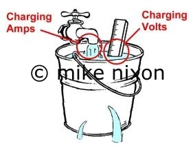
Also, here's a nice write up from a bike mechanic about Ammeter function: Ammeter Ethic @themotorcycleproject his bucket analogy is easy to get one's head around:
Also, here's a nice write up from a bike mechanic about Ammeter function: Ammeter Ethic @themotorcycleproject his bucket analogy is easy to get one's head around:
'stock,
That's a great explanation! That with your explanation of the alternator above in how it is able to quit charging when the battery has reached it's charge level help make it all make sense. In a way, a ammeter is kind of a geeky thing in regard to knowing exactly what the current is at any given point in time, the ammeter will reflect that.
Interesting to note that most recent modern cars don't have a ammeter or a voltmeter, it seems something most people don't even need. When your battery doesn't start the car it's not being charged...
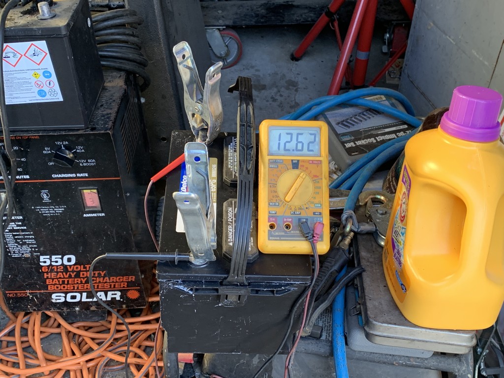
Made some progress today, but before I flip the key, I want to make sure I have things correct.
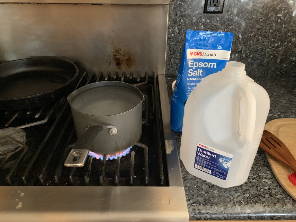
First I needed to refurbish a 12volt battery, so I got some epsom salt and distilled water and made some homebrew electrolyte...drained and replaced and charged at 12v 60amps, and it was holding 12.62.
NOTE: this is a good time to toss some salt into my wounds with a bit of irony...you can barely see the left meter on my battery charger behind the cables is a voltmeter, but the right meter is an ammeter. There has to be some irony in there wtih the 6v->12v conversion, given the generator used an ammeter and the alternator is better suited to a voltmeter. I actually bought this for the 6v capability, I didn't have one. $50 on craigslist.
I got the generator out, that old piece was pretty grungy around the bracket...LOL no worries...I cleaned it up with a wire brush.
I didn't get a pic of the alternator though, I needed to use a couple washers with the bracket to line up the belt properly. Used the same belt that the generator used.
I think I'll replace the belt, but the old one is on there for now.
Ok, the alternator connector 1 is looped to the battery post, I connected the old armature wire from the generator to the battery post as well.
I disconnected all the field and armature wires, and connected the armature wire to the bat terminal and checked everything with a volt meter before and after. Now the battery post of the alternator goes to the ammeter and then to the battery post on the starter, which goes to the + on the battery.
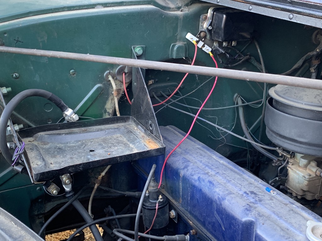
Looking for some feedback here. Here's the new coil, although it's loose in the holder, I will fix that, and you can kinda sorta tell that the 2 right connectors on the old voltage regulator and disconnected, but the middle one was the armature, and it's now going to the alternator battery post.
Per the conversation above with 'stock and 'beater, the coil - is going to the distributor, and the the positive is going to the reducer, which I mounted off the volt meter, and the other side goes to the ammeter, at least I'm believe it is as that was how it was wired for 6volt.
The one wire I don't have connected is the number 2 connector from the alternator. I was thinking this needs to go to the ignition. Is that correct?
I also have the fuel gauge reducer to install in addition to confirming the wiring and connecting the number 2 connector of the alternator.
You cannot simply connect the old ARM wire to the Bat terminal on the alternator. The Bat terminal on the alternator needs a path to the battery. As we discussed above that path could be through the Ammeter or via entirely new wire.
I recommend that you spend some time reading and/or studying YouTube videos on how the GM 3-wire alternator functions in its native home a - 64-72 GM car/truck. It is important to get your head around an electrical project before undertaking it. Its even more important when the project involves adapting a newer component into an older vehicle.
Heres a great video on where and why the three wires are placed in the native installation: GM 3-Wire Alt Video
Next I would do some reading on 12 volt conversions and Delco alternator wiring. Some of these conversion recommendations seem to specifically avoid working behind the dash board - suggesting that the ignition circuit running from the key to the coil should be involved. I am not a fan of this approach because it can come with unintended consequences. There are better places to pick up key-on 12 volts behind the dash. Moreover, the exciter wire provides the fault light feature. There are simple jewel indicator lights readily available that can be mounted in or under the dash.
You cannot simply connect the old ARM wire to the Bat terminal on the alternator.
Sure I can! I think you may have misunderstood. I used the armature wire, but I'm only using the wire in the harness to run from the battery post on the alternator to the battery out on the voltage regulator. It's not using the voltage regulator. As I mentioned I will just crimp a coupler connector and remove the voltage regulator all together, but it's not being used as both the armature wire running from the alternator and the line going out of the voltage regulator are using the out as a common post to connect. It's only a wire! The voltage regulator is not being used at all.
Originally Posted By: stock49
The Bat terminal on the alternator needs a path to the battery. As we discussed above that path could be through the Ammeter or via entirely new wire.
If I'm not mistaken, the battery out from the voltage regulator actually goes through the ammeter to the battery. If you look at the wiring diagram for a 1946 truck the wire goes from the voltage regulator battery out to the ammeter, to the starter, to the battery.
Originally Posted By: stock49
I recommend that you spend some time reading and/or studying YouTube videos on how the GM 3-wire alternator functions in its native home a - 64-72 GM car/truck. It is important to get your head around an electrical project before undertaking it. Its even more important when the project involves adapting a newer component into an older vehicle.
I agree and I did watch several videos, but think you misunderstood what I was saying. Sorry if I confused you.
I'm only using the wire, I could have just as easily used the field wire, it also went from the generator to the field in on the voltage regulator, I could have used it and moved it over and connected to the battery out wire also.
Originally Posted By: stock49
There are better places to pick up key-on 12 volts behind the dash. Moreover, the exciter wire provides the fault light feature. There are simple jewel indicator lights readily available that can be mounted in or under the dash.
Yes, this is what I was explaining above, most run the field to the ignition switch, otherwise the engine won't turn off when you turn the key off.
Sure I can! I think you may have misunderstood. I used the armature wire, but I'm only using the wire in the harness to run from the battery post on the alternator to the battery out on the voltage regulator. It's not using the voltage regulator. As I mentioned I will just crimp a coupler connector and remove the voltage regulator all together, but it's not being used as both the armature wire running from the alternator and the line going out of the voltage regulator are using the out as a common post to connect. It's only a wire! The voltage regulator is not being used at all.
Excellent! Glad you got your head around this. I did the same thing but kept the voltage regulator housing in the mix (as a prop) for stock looks: It just shunts the Arm and Bat wires together. And a I used the Fld wire as a body ground.
Originally Posted By: Keroppi
Yes, this is what I was explaining above, most run the field to the ignition switch, otherwise the engine won't turn off when you turn the key off.
Exactly. There are three posts on the stock ignition. Bat, Aux1 and Aux2. If the ignition coil is wired to Aux1 the exciter wire has to go on Aux2. They cannot share a post.
Exactly. There are three posts on the stock ignition. Bat, Aux1 and Aux2. If the ignition coil is wired to Aux1 the exciter wire has to go on Aux2. They cannot share a post.
This is the missing piece to the puzzle! Thank you! I will need to look at the ignition switch and see what is what.
Shamefully I will admit that I started to watch this video and didn't finish for some reason...but this I believe is the video you were talking about.
EDIT: I know now why I didn't finish watching this video, there is one difference in this wiring that is not the same for my truck, that being that the solenoid goes to the ignition for all non-floor pedal trucks. But for trucks with the floor pedal starter, the solenoid is inside and we don't have that position on the key. On the AD trucks they use a push button, don't they? I know some of the early ADs used a floor pedal, I'm not clear when that changed.
Which reminds me, I need to get a light bulb? I'm listening to the video now and he's got a bulb as I've seen so you can see if the alternator is charging or not.
EDIT: I just found this bulb that I will stop and get.
FYI, I really appreciate the help that I've gotten here. 'stock, 'beater, 'mick, you folks have been most helpful as I sort through this stuff with my 'ol '46.
I just joined the Inliners, something that was probably way overdue, but something that seems fitting.
I previously had a very bad experience with the VCCA, the moderator over on the VCCA Chat Forums is an Internet Nazi. Stovebolt is not my kind of place either, too many rules, too much heavy handed moderation, it just doesn't suit me. ChevyTalk has quite a bit of rules and guidelines also...but it has been here on the Inliners that you folks have offered me help and have come through with much of the information I've needed on my pickup. H.A.M.B. has also been good for me, but the Antiquated forum is not the mainstay there, but still the people are nice and helpful as well.
I don't know if it's possible to change my username to Traditional Toolworks or not? That is my company name. I'm ok with Keroppi, that's what I call my pickup, but would prefer Traditional Toolworks. Some places don't allow company names, I know ChevyTalk is like that.
Well, I had to order the light at O'reily Auto, and it came in but is kind of interesting, it's not an incandescent bulb with a metal socket, it's a modern style bulb that pushes into a plastic socket.
I have what I need, just need to get down to my yard and wire it up so I can test it. I still need some of the bulbs for the stop and turn signals..
I got the ignition hooked up, lost one of those little nuts, but robbed one from the Acc which was not being used.
Wasn't sure about the fuel gauge though. I have a voltage reducer, but I can see the 2 wires going to the gauge, but wasn't sure which is the correct side.
I'm at home now looking at the wiring diagram and one side of the gas gauge should be going to the ignition on that same post I connected the alternator to, through the light.
I need to connect the reducer on that side, I believe, as it goes to the coil. Is that correct?
The other side goes to the gas tank, but I'm not sure it's hooked up, and it could be to the old tank still. I have another tank in the back of the bed which is the one being used.
I'm at home now looking at the wiring diagram and one side of the gas gauge should be going to the ignition on that same post I connected the alternator to, through the light.
I'm pretty certain this is correct, but what I believe is the fuel gauge behind the dash seems to have continuity to both wires at the ignition post...something seems wrong. One side should go to the gas tank sender. I don't think that should have continuity to the ignition post. Hmmm...
I need to ponder a bit, but will have until next weekend most likely, so will see what Jim Carter says.
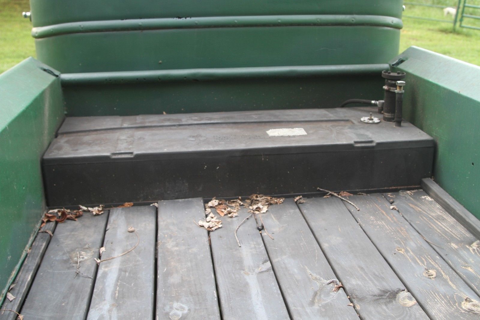
Prodding along I have to ponder that nothing is hooked up to the gas tank, which is in the bed of the pickup:
If I'm not mistaken a wire needs to be connected to the round chrome disk next to the filler tube. I'm pretty sure that is the sender unit.
I think I really need to get the gauge cluster out of the dash to be able to see what is really going on.
Has anyone ever taken a gauge cluster out of a dash on an AK Series? I believe I have asked this before. This might be a question of Jim Carter, I might be pushing the limited exposure on the Inliners. Even searching on Stovebolt and ChevyTalk rendered nothing.
Surprised that nothing in the shop manual explains how to get the gauge cluster out. I've been told there are a couple bolts on the back side, but I haven't been able to get to them yet.
EDIT: in case anyone reads this in the future, the voltage reducer/resister goes to the (E)mpty side of the fuel gauge. And both posts will show continuity, just different levels as it will pass through the gauge, so I was told. Steve at Jim Carter Truck Parts agreed with my assessment, that a wire should be connected to the sender on top of the gas tank, and that I should ground one of the screws to be safe.
Last edited by Keroppi; 10/07/1906:11 PM. Reason: Talked to Steve at Jim Carter Truck Parts
Still haven't been able to get down to my truck again, been busy with a short contract that landed in my lap...I've been desperate for work, so this is a good thing...this Sat. the local Inliners are meeting for breakfast in Milpitas, gonna try and meet up with some of the local boys, and make some inline 6 friends...maybe I can get down to my yard after...
Surprised that nothing in the shop manual explains how to get the gauge cluster out. I've been told there are a couple bolts on the back side, but I haven't been able to get to them yet.
EDIT: in case anyone reads this in the future, the voltage reducer/resister goes to the (E)mpty side of the fuel gauge. And both posts will show continuity, just different levels as it will pass through the gauge, so I was told. Steve at Jim Carter Truck Parts agreed with my assessment, that a wire should be connected to the sender on top of the gas tank, and that I should ground one of the screws to be safe.
Shouldn't have take the gauge cluster out. You can get to all the wires through the service hatch in the firewall.
Glad to hear that you have a service manual in hand. It describes how to trouble shoot the fuel gauge. In particular one cannot test continuity in the sender wire while it is attached to the gauge and the sender.
That looks like a plastic tank. If so the ground wire to the sender body is a must.
Shouldn't have take the gauge cluster out. You can get to all the wires through the service hatch in the firewall.
I wish that was the case. No access from the firewall on the '46, that is something that changed on the AD First Series.
I was actually thinking about cutting a hole in the firewall, I have the voltage regulator there which is not going to be used.
Originally Posted By: stock49
Glad to hear that you have a service manual in hand. It describes how to trouble shoot the fuel gauge. In particular one cannot test continuity in the sender wire while it is attached to the gauge and the sender.
I'll go look in there again, I have the 42/48 shop manual. I didn't see it...🤔
Originally Posted By: stock49
That looks like a plastic tank. If so the ground wire to the sender body is a must.
Actually it's metal, just dirty. If I ever get this beast running again I'll probably redo the bed and build a cover for the gas tank to have some storage, thinking about a wooden toolbox type cover.
That looks like a plastic tank. If so the ground wire to the sender body is a must.
stock,
You're right, that is a plastic tank. I thought I thumped it before and it was steel, but it is plastic, it's hard, but it's plastic. There is nothing connected to either the tank in the rear or the tank under the seat, so I figured it was probably safe to try and fire it up.
I connected a battery and it cranked really strong, but it didn't fire. I looked and I have the negative side of the coil going to the distributor, and the top of the coil going to the top of the distributor, but I didn't check to make sure those cable plugs are seated inside well, so I will do that tomorrow. I wasn't sure if I had the coil connected backwards, but looking online it looks like the negative side does go to the distributor, or am I wrong?
As a data point, the light is on that is connected to the ignition from the alternator, and it dims a lot when it's cranking, but doesn't go out completely, but I think that is normal until the alternator is running faster with the engine.
The positive side of the coil is going to the voltage reducer and then to the ammeter, I believe, that was the wire that was connected to the coil previously. I don't think it matters what side the wires go on for that voltage reducer, it looks like a resistance spring of some type. I will ask that to Jim Carter.
Seems it must be those coil connections from the top of the coil, I will try to go back and look at that tomorrow.
FWIW, I had breakfast with the Bay Area Inliners in Milpitas, and we drove down to Aroma, between Gilroy and Watsonville, lots of cool cars at a HUGE show there and the owner of the shop there had some really cool Inliners...one was a really cool old race car with a 235 hemi in it and a Wayne head. He had a second Wayne head, I was told those are used by people that race Inliners.
I will check those coil connections and see if I can get spark at the spark plug. One nice thing about the floor starter, you can do that from inside the engine compartment.
Very odd, seems like it was a fuel delivery problem, but after giving it a couple shots of starter fluid it was pumping ok. when I pull the choke the bubble gets about half full...so it seems to work when it runs faster and get more fuel...
I think adjusting the valves is going to be in my future.
I think I also need to replace fuel lines and/or filter as well as grounding and running the line to the fuel sender, as suggested by stock. First thing I need to get a battery that will fit that tray, and relinquish this one for the trailer winch.
Congratulations ! Yes I think valve adjustment is in your future. It sounds a bit like a thrashing machine but some of it could just be the video. Make sure you check the oil to the rocker shaft. That could be some of the noise. These often plugged with sludge from old oil. They even used to sell after market oiling kits to bypass clogged passages. At least you now have a runner to play with, much more fun.
"I wonder if God created man because he was disappointed in the monkey?" Mark Twain
Congratulations ! Yes I think valve adjustment is in your future. It sounds a bit like a thrashing machine but some of it could just be the video.
I think it just needs adjustment to get it dialed in...
Originally Posted By: Beater of the Pack
Make sure you check the oil to the rocker shaft. That could be some of the noise. These often plugged with sludge from old oil. They even used to sell after market oiling kits to bypass clogged passages. At least you now have a runner to play with, much more fun.
I will definitely be checking all of that out when I adjust the valves. I want to get a valve cover gasket before I do that, I know it will probably come off in pieces...but for mentioning it, now it will come off nicely in one piece...
I have a lot of stuff to do, wiring, body work, bed replacement, windshield crank, et al...that is all in addition to basic tune-up stuff...lights, hoses, etc...I'm sure you know the list pretty well...
Today it gets a new battery, one that will fit the tray...
I have 2 primary areas where rust is really bad. Both door bottoms need to be replaced. And the bottom rear of the cab, wasn't until I pulled the seat that I could see daylight from the inside. With the seat in place no light when under the truck...some pitting along the center bead of the cab and some other rust, but I'll need to clean some of the paint off. Point being that I have my work cut out for me...